This is part two in the series of posts describing the project to rebuild the Portabee. This part will talk about the changes I've done to the motor housing, the motor couplers and heated platform support improvements.
If you haven't read part one, you can find it here: http://www.igorkromin.net/index.php/2015/03/03/rebuilding-the-portabee-3d-printer-part-1/.
Now to continue where the first part left off...the motor housing. The original housings that Portabee had were quite minimal and left the tops very open. This allowed bits of plastic and dirt to quickly build up on top of the z-axis motors. When I redesigned the base components, I've covered the exposed areas of the housing to be completely sealed except on the bottom and one of the edges where the wiring comes out.
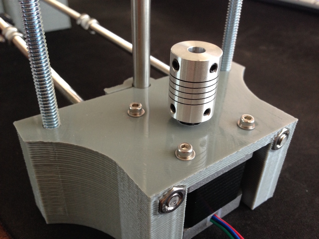
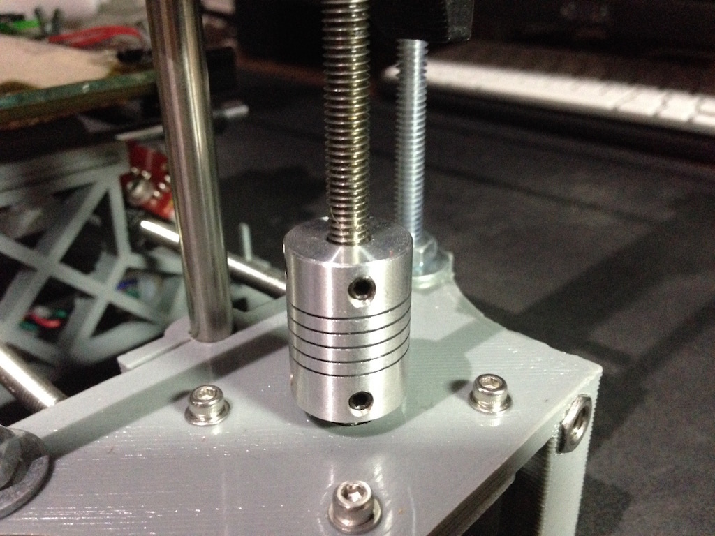
The z-axis has always given me trouble with the threaded rods popping out of the original couplings. To remedy this I got a hold of some aluminium couplings that could be secured to the motor shaft and the threaded rod with no chance of popping out. These couplings use two grub screws at a 90 degree angle to securely stay in place.
The couplings have a spiral cut around the mid section to give some flexibility, so they aren't completely solid.
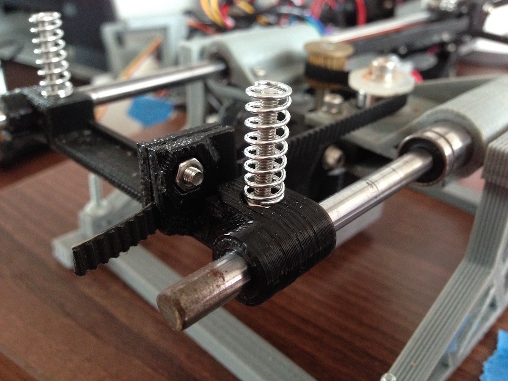
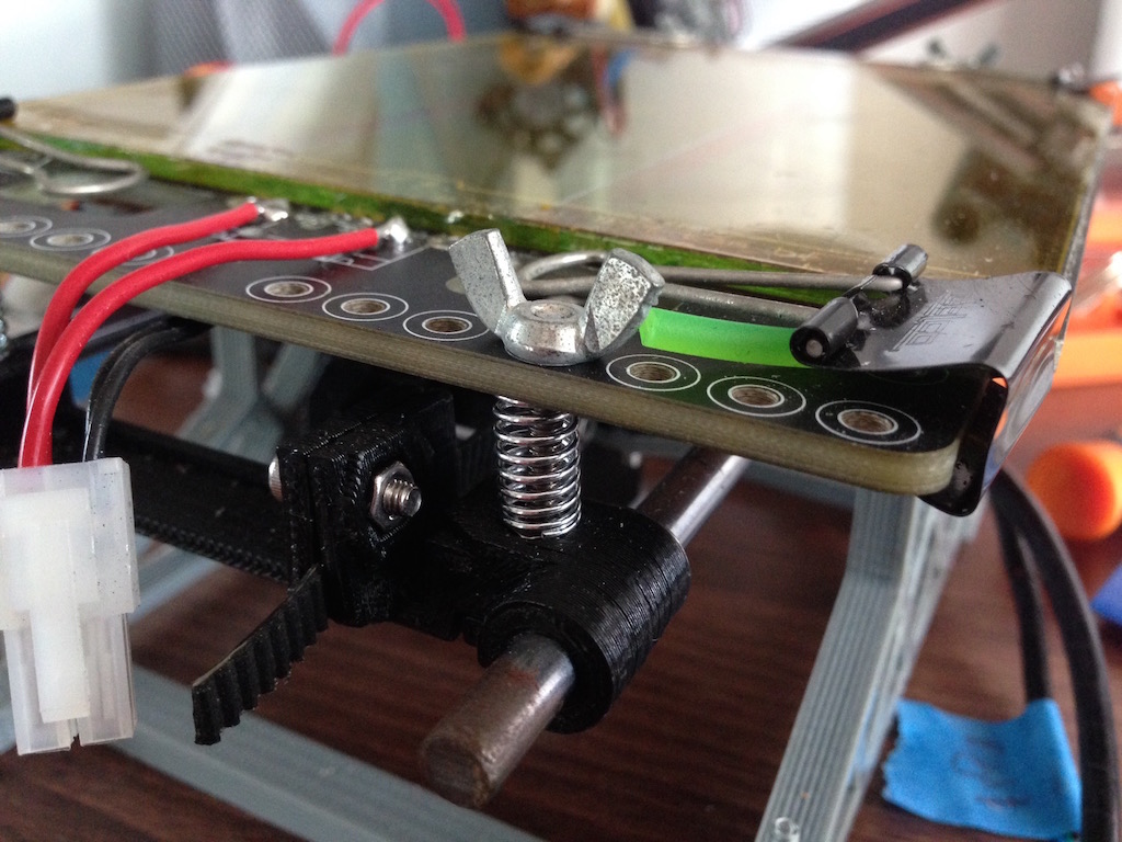
After the couplings, the next most annoying thing about the original Portabee was how difficult it was to adjust the heated print bed, and you have to adjust it often. I've already replaced the standard nuts with wing nuts on a previous occasion, but this time I went further by putting in springs under the bed and removing the nuts that sit just underneath it. The springs constantly push up on the bed so the additional nuts are not required and due to this upward force the top wing nuts are the only adjustment points. This is a very simple mod, but makes it extremely easy to adjust the level of the printer bed.
That covers the minor modifications that are for convenience sake. The next part will talk about the changes to the y-axis.
The third part is now posted, you can read it here: http://www.igorkromin.net/index.php/2015/03/05/rebuilding-the-portabee-3d-printer-part-3/.
-i
