This is part four in the series of posts describing the project to rebuild the Portabee. This part will talk about all of the rewiring work.
If you haven't read part three, you can find it here: http://www.igorkromin.net/index.php/2015/03/05/rebuilding-the-portabee-3d-printer-part-3/.
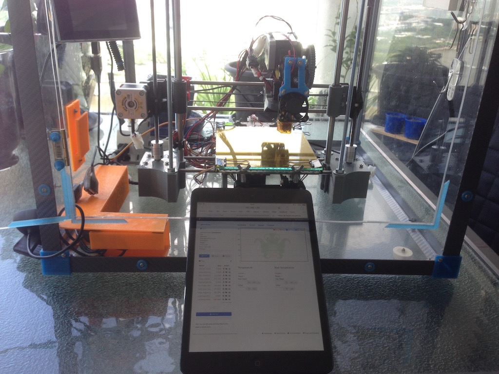
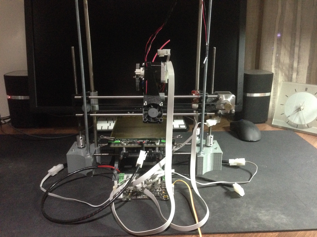
Before I rewired all of the motors, extruder and switches, I had to make sure that the printer was working fine after other modifications were completed. I hooked up the printer as per its original setup with a Raspberry Pi inside the printer box running OctoPrint. It seemed to work, which was a relief considering the printer was out of commission for three months!
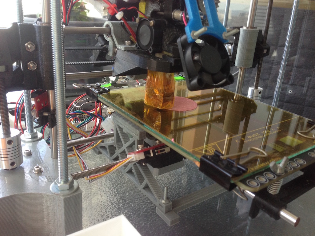
Once I verified that the printer was functional, it was time to take care of the mess of wiring...
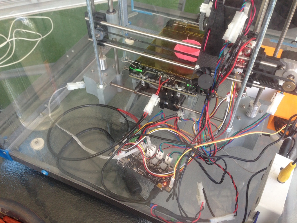
I chose to go for simple grey ribbon cable to both replace the old wiring and extend its length in some places. Using a ribbon cable also meant that I could have multiple cables 'combined', for example, running a 10 strand ribbon to the extruder assembly, this would have enough wires for the extruder motor, heating element, temperature sensor and the cooling fan.
I bought two meters of 28 strand ribbon cable to complete this job, by the time I was done there was still over half of that remaining.
Where possible, I disassembled the original plugs that my Portabee had and soldered ribbon cable wires to those, then reassembled them again. In some cases like motor connectors and the extruder heater, I had to purchase new connectors.
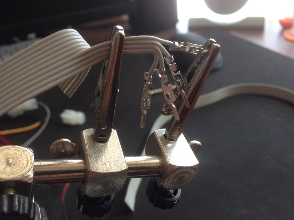
Using a soldering stand made rewiring and soldering significantly easier.
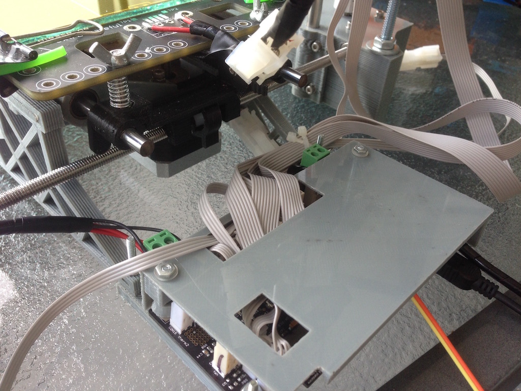
After a few hours of work, all of the re-wiring was completed. I didn't change wiring on the extra cooling fans at this point as those connect to the wiring inside the printer box, however this is something I will be coming back to. I also chose not to rewire the heated bed due to a heavier gauge of wire used there, however I did turn it around so that the wiring was on the back side of the printer, this helped with the cable management. The end result was amazing!
I've had a cover for the Gen6 board from before, I simply repurposed it, however, I did attach it to the y-brace.
...and finally the finished project back in the box...
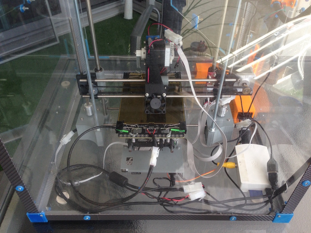
There are a few things that I need to finish up with this rebuild like printing new bracing to hold the printer in place inside the box, these will be attached to the new frame that surrounds the z-axis. I also need to rewire all of the fans inside the box and move the filament feed from the side to the top.
-i
