I wanted to stay with the Apple/OS X platform since all of my work and personal stuff was on my MacBook Pro, and after weighing up the cost of buying a real Mac Pro vs building a MacPro hackintosh, the choice was quite easy, it was the hackintosh approach.
I've looked around on eBay for a few weeks, and finally found a broken (lightning strike) MacPro for $93, so I picked it up and started with trying to work out how I can make standard off-the-shelf components fit inside.
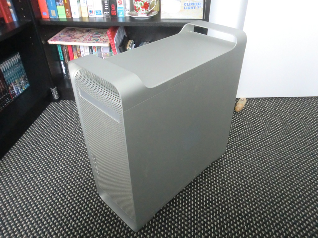
As has been pointed out this is an Apple Power Mac G5 case, not a Mac Pro case. Both of these cases are very similar however so the rest of the article should make sense no matter whether you got the former or the latter case for modding. The most important thing to remember is to enjoy your modding project and have fun doing it!
This was the case when I got it.
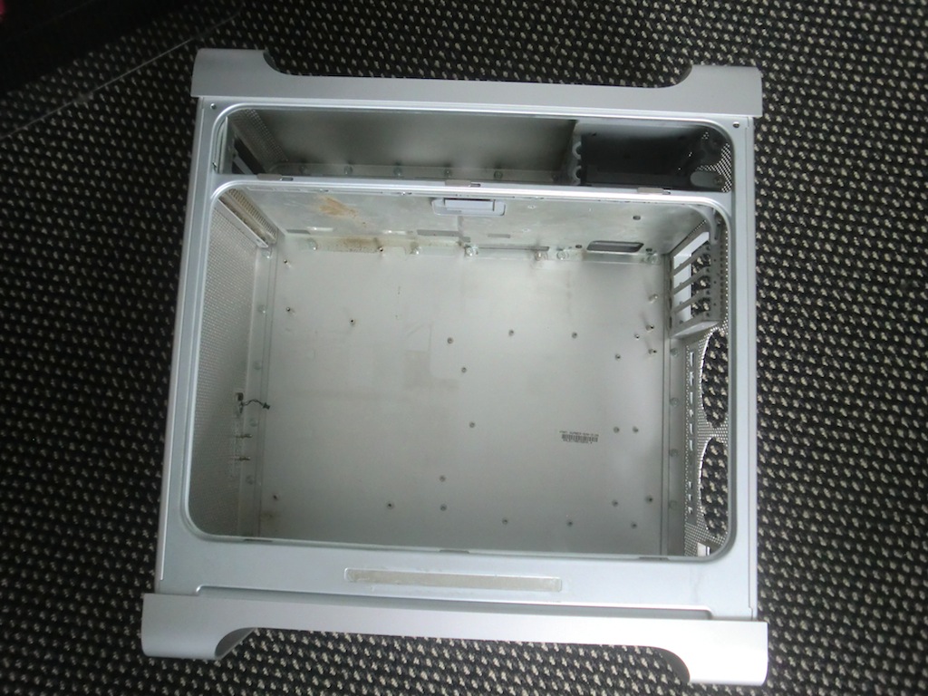
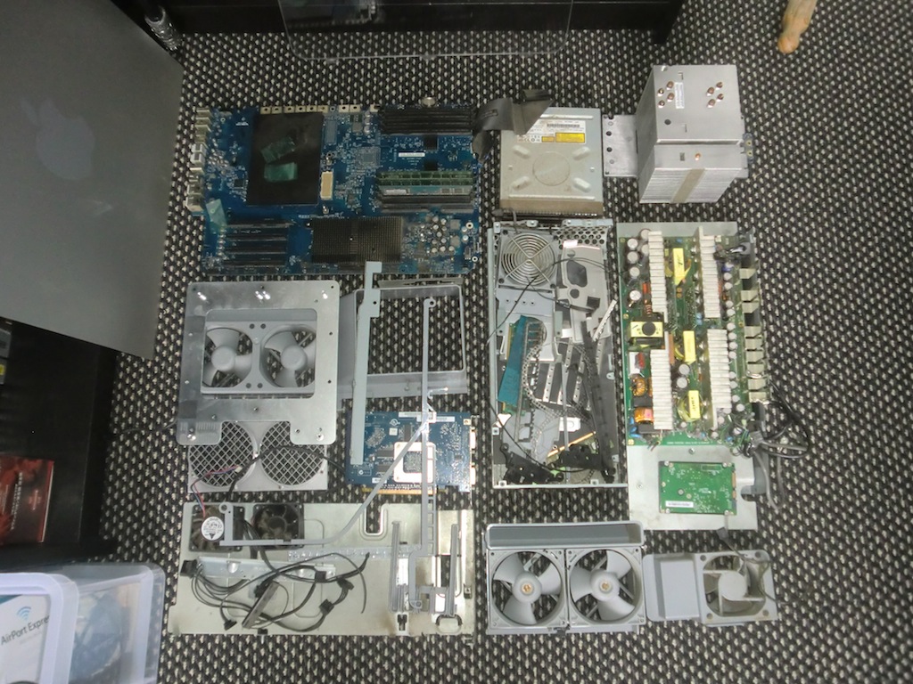
Pulling all the parts out of the case took some time and some had to be forced, but finally they all got removed.
All the gutted parts.
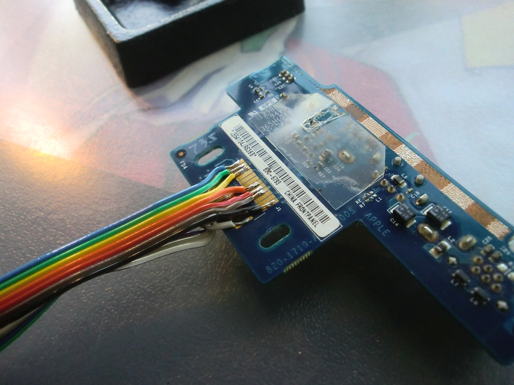
The front panel connector on this G5 was a bit tricky. However, I found the G5 Front Panel pinout here: G5 Front Panel Pinout
The pin-out is as follows.
01 02 03 04 05 05 06 07 08 09 10 11
12 13 14 15 15 16 17 18 19 20 21 22
01: Audio Left
02: Audio GND
03: Audio Right
04: ???
05: FIREWIRE GND (double)
06: USB VCC (+5V)
07: GND
08: GND
09: FIREWIRE TPB-
10: FIREWIRE TPB+
11: LED
12: Firewire FW802C IC VDDA (+3.3V)
13: ???
14: GND
15: FIREWIRE VCC (double) (+12V)
16: GND
17: USB D-
18: USB D+
19: GND
20: FIREWIRE TPA-
21: FIREWIRE TPA+
22: BUTTON
I've wired up everything apart from the Firewire as I didn't have a need for that.
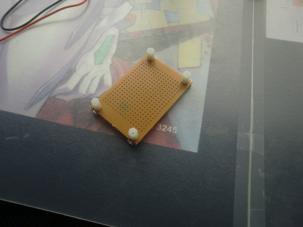
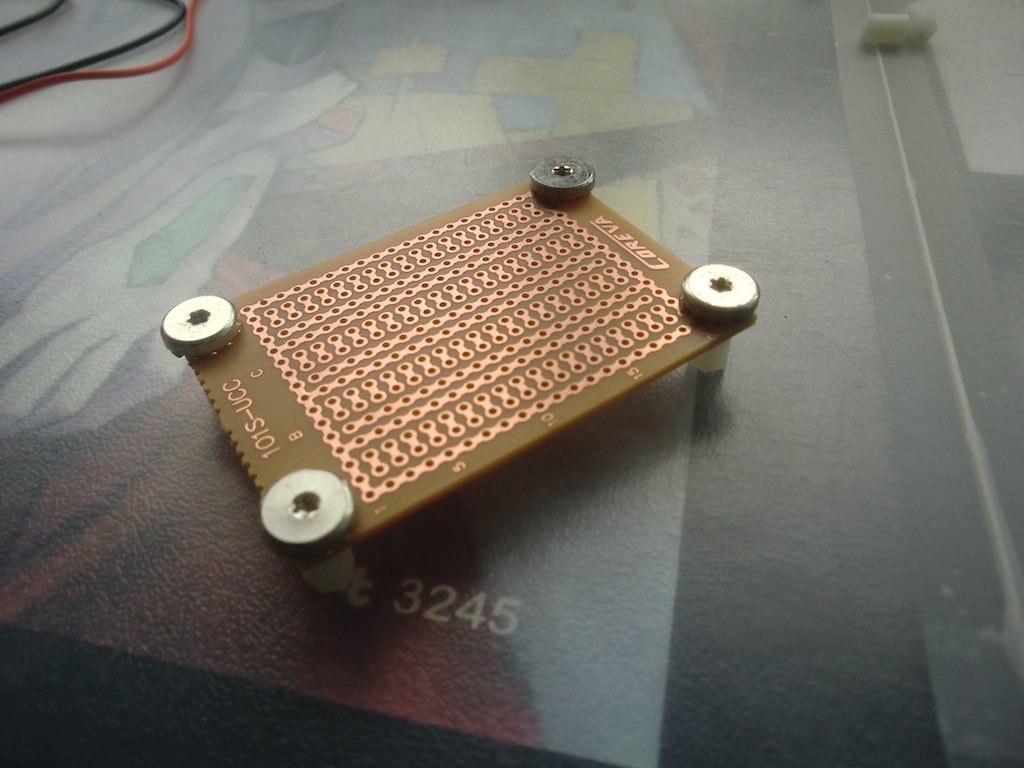
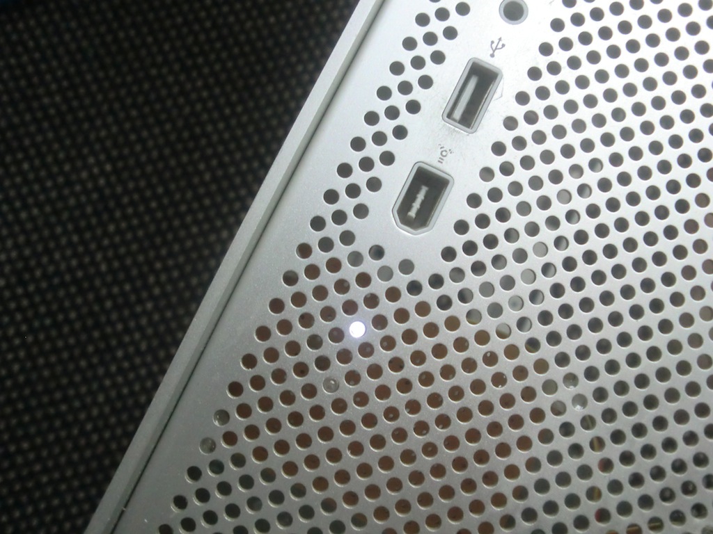
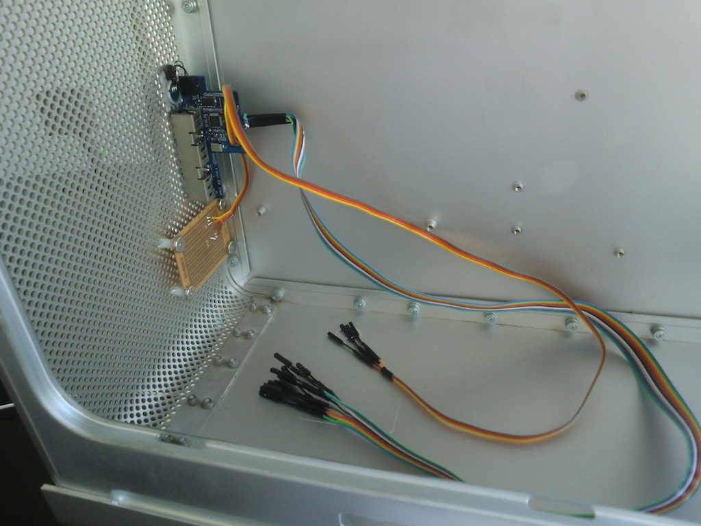
The front panel connector power LED for this G5 model will not work, so I thought why not add my own and while at it, add a HDD activity indicator light as well. I got a project board, added some spacers to it using some of the original screws and connected two LEDs, one white for power and one blue for the HDD activity.
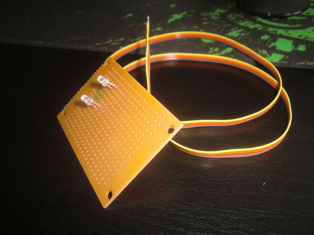
Testing out the LEDs with a multimeter.

I used some two part epoxy to fix the spacers of the project board PCB to the front panel of the MacPro. All of the wires got the 1pin Dupont connectors soldered to their tips so they can be plugged into the motherboard later on.
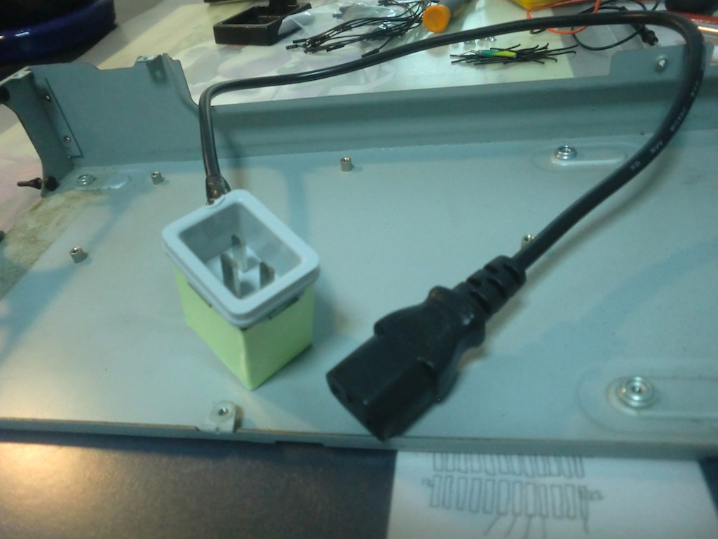
I wanted to reuse the original power connector on the back of the MacPro, so the power supply got ripped apart and the power socket pulled out. Then, I cut up a power cable I had already and connected the wires to the power socket from the existing power supply. Same coloured wires were connected to the same coloured wires of course, then heatshrunk. This will let me plug in a standard power supply later on inside the case while having the Mac Pro style power cord on the outside.
Continue reading the next part of this post: Building a Mac Pro Hackintosh - Part 2 - Cutting and preparing the case
-i
