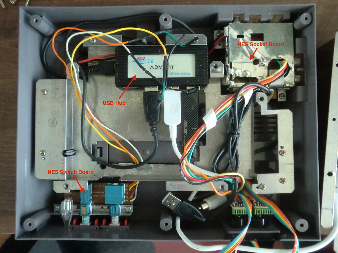
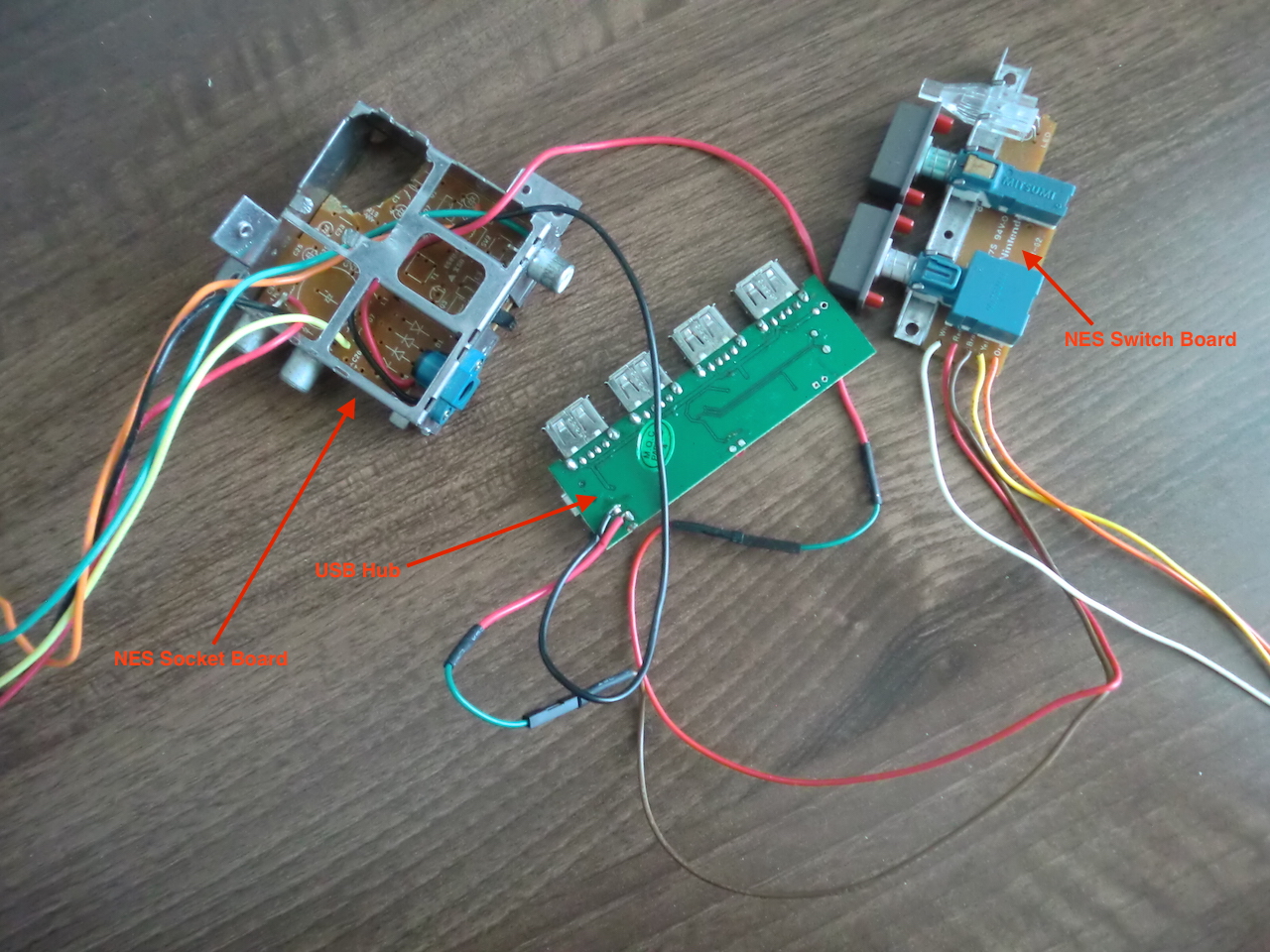
I've put together a diagram of the wiring as well as some close up photos of where I connected my wires on the original NES boards. There are three places for wiring: NES Switch Board (at the front of the NES), NES Socket Board (at the rear of the NES) and the USB hub (at the power socket).
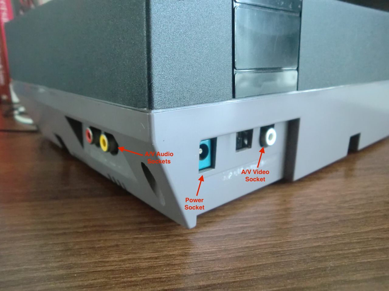
Keep in mind that the goal for the original project was to use all the existing sockets, this meant that the HDMI connector could not be used and the audio had to be connected to the A/V sockets by splitting the stereo jack that is plugged into the RPi.
If you just want to look at the photos for this article:
♣ Open image gallery
Here's what it all looked like when I took the case off. The Raspberry Pi has since been repurposed and is no longer inside, but the rest of the wiring remains.
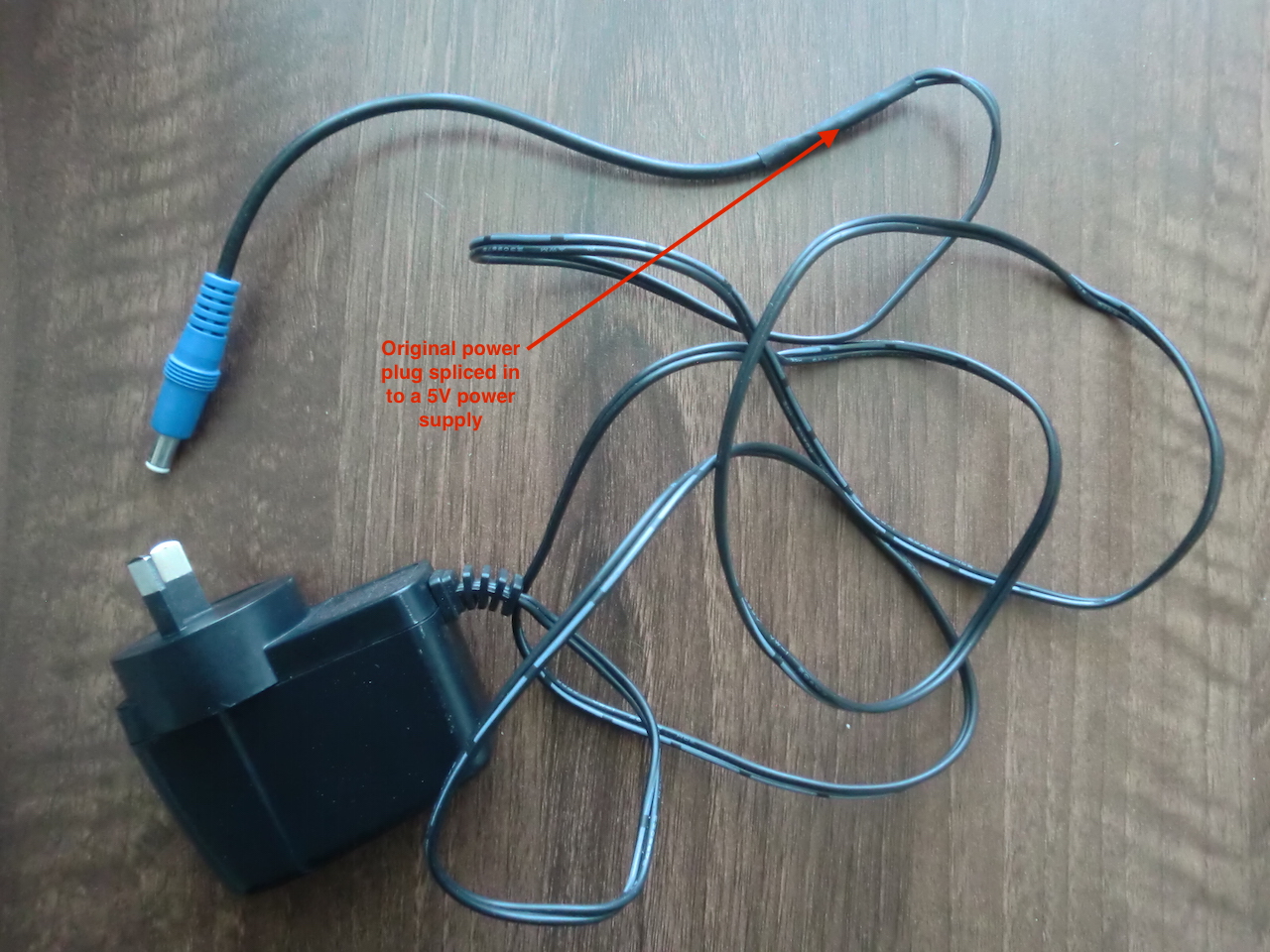
The 5V power supply that I used for the USB hub has has the original NES connected spliced in instead of whatever plug it had previously.
Just a quick reminder of what the sockets are on the rear of the NES...
Now lets see the boards that are wired up (don't forget that I had to strip all of the components apart from the sockets from the original socket board)...
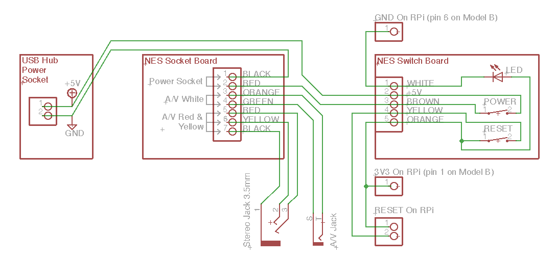
In terms of a rough schematic, it looks like this...(you do need a 10k resistor inline with the white/gnd wire going from the LED to the 3v3 pin on the RPi, that resistor is not shown here).
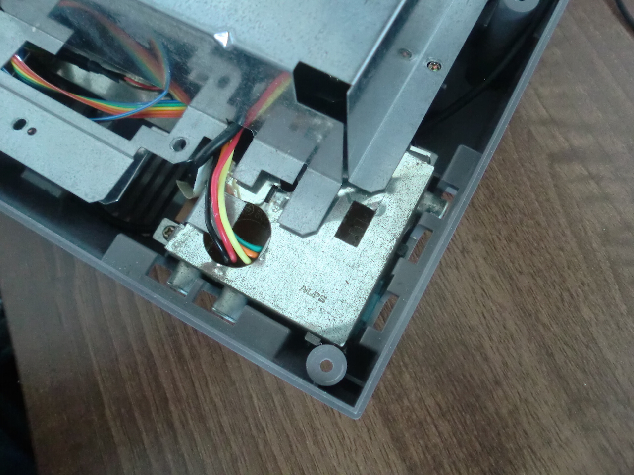
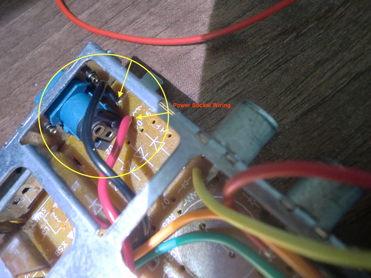
Here's a closer look at the power socket wiring. Keep in mind that the red wire connects to the 'red' pin hole on the switch board, then the 'brown' wire is the one that connects to the USB hub positive terminal. This way the power to the USB hub can be switched on/off.
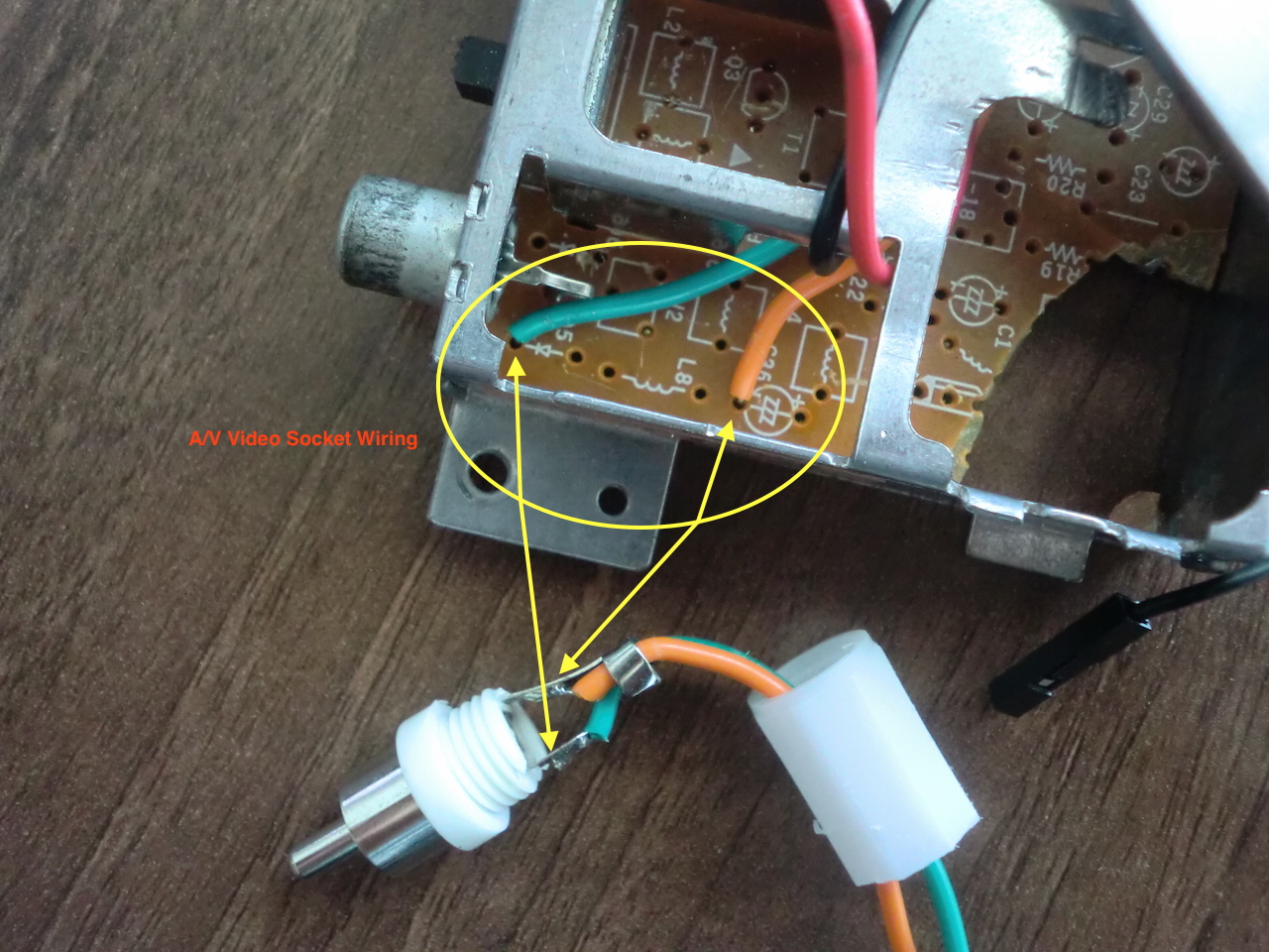
This is the video plug wiring.
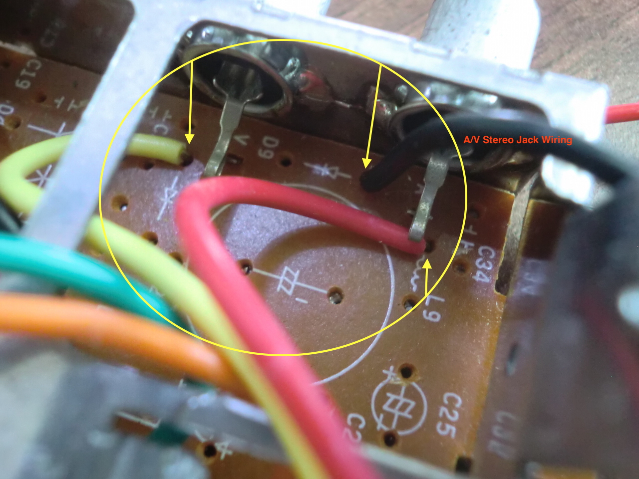
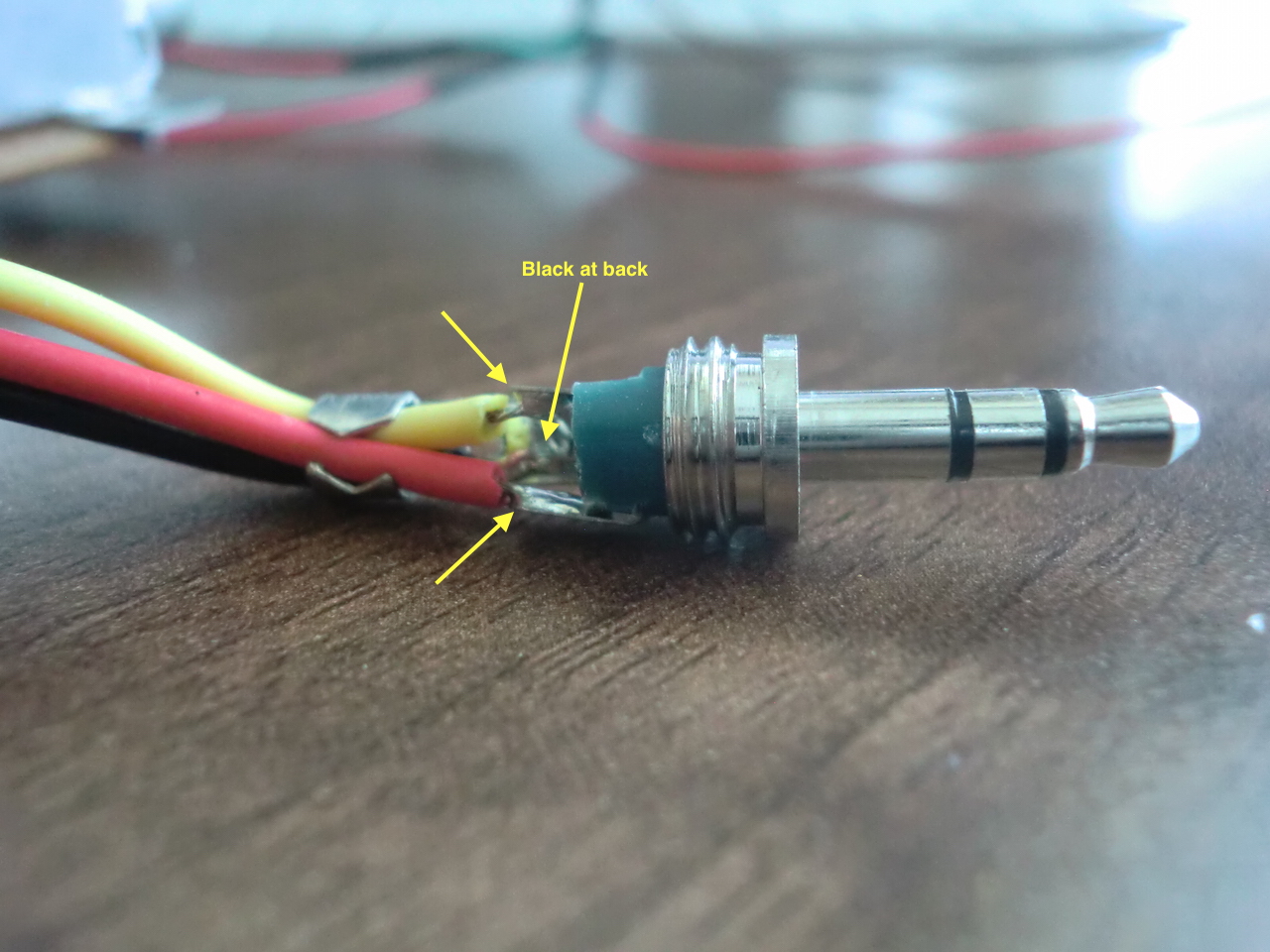
...and finally the stereo jack wiring.
That's all there is to it. Not going to go into controller wiring since that is covered sufficiently already.
Enjoy!
-i
