When mine arrived, I didn't really know what to use it for, but then it hit me: I can build an emulator box for all the NES and SNES games that I loved to play as a child.
The goals for this project were:
- Build an emulator box to play NES/SNES games
- Use the original NES case
- Use the original NES controllers
I've revisited the wiring descriptions and put together a diagram that should make it easier to follow how everything was connected. You can find that information here.
I picked up a non-working NES from eBay, it came with two controllers and a game. So much for the game, it will be of no use, but the rest is what I needed. The NES is really easy to take apart and just uses standard screws.
Here it is taken apart.
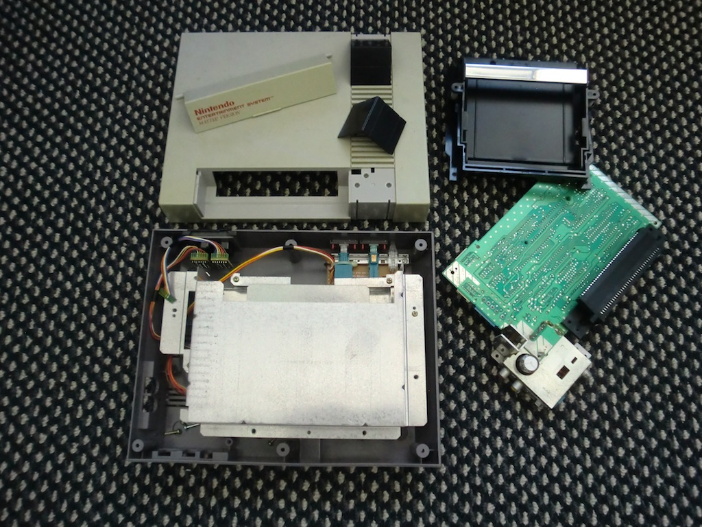
The power and A/V connectors were attached to the main circuit board block, it was a bit of a pain to pull them out and a part of the PCB got damaged in the process. No big deal on the damage, I didn't need the whole PCB intact.
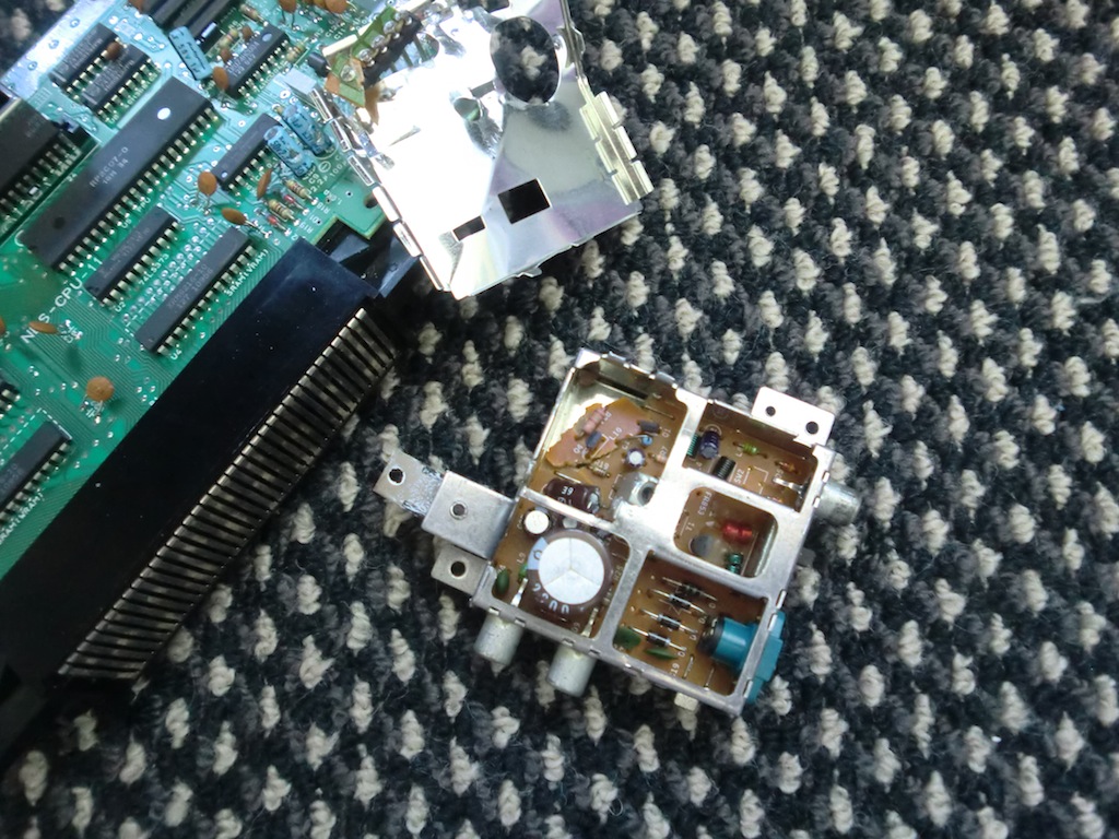
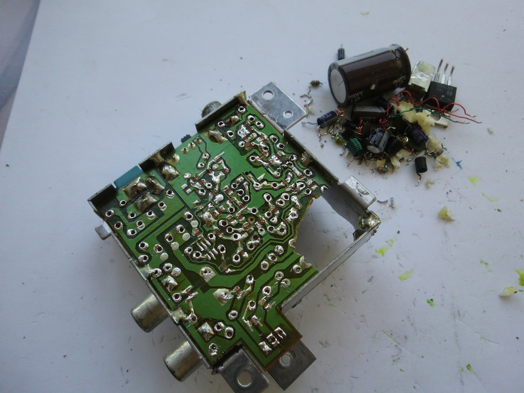
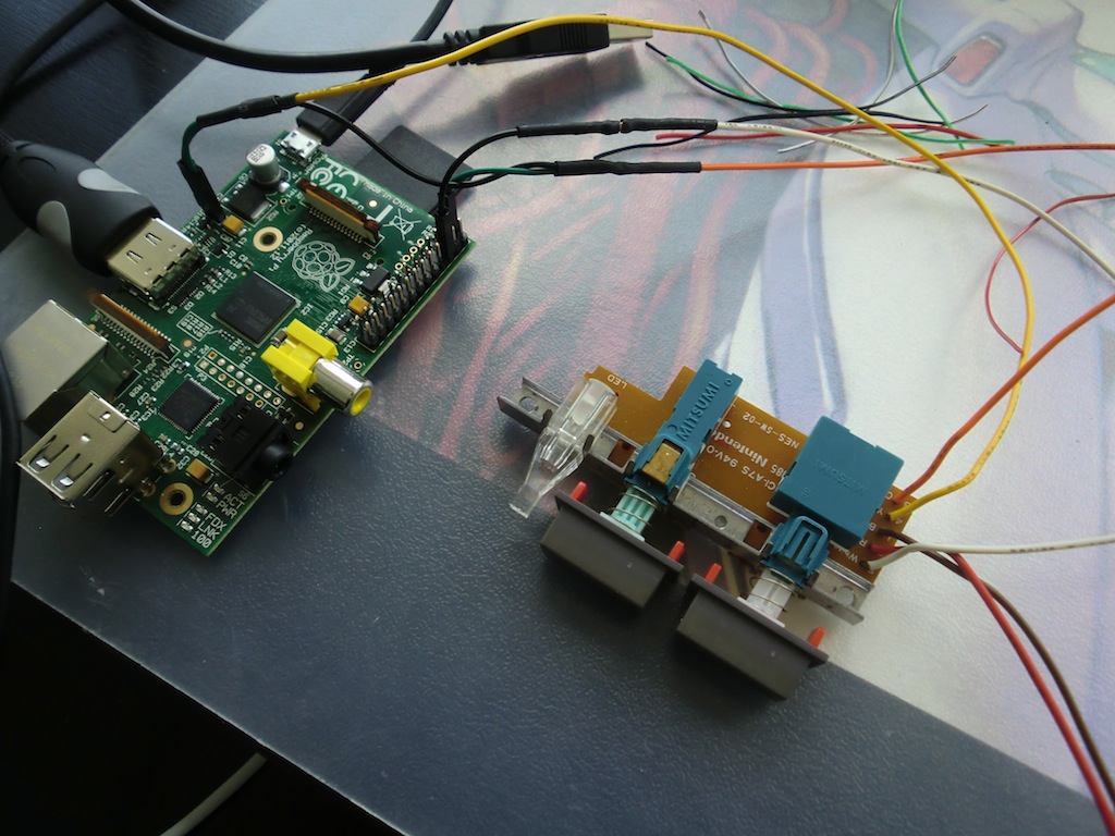
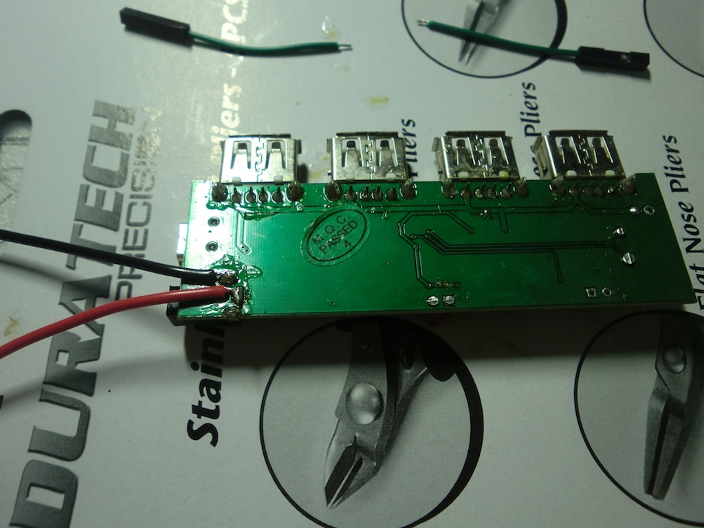
I desoldered all of the components on the A/V PCB so that I can solder in my own wiring later.
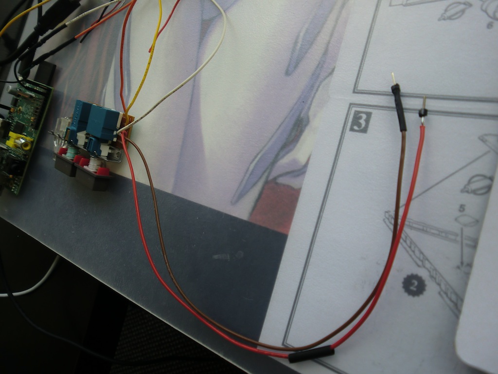
The front panel with the on/off and reset buttons and the on LED is removed. I added single pin Dupont connectors on all of the wires except for the power button, there I soldered on single pin headers. The idea with the power button is to have the pins plug into the wiring I will have running from the power socket and either close the circuit or not.
Testing out some of the connections.
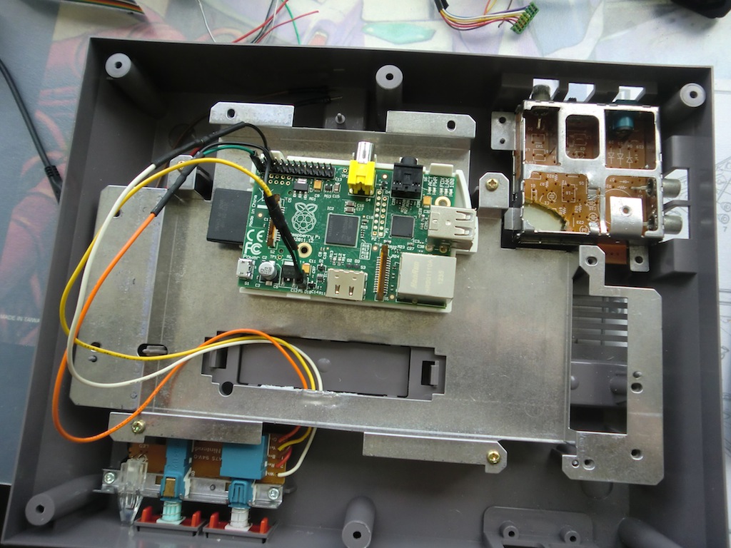
Everything from the front panel screwed back into place and connected.
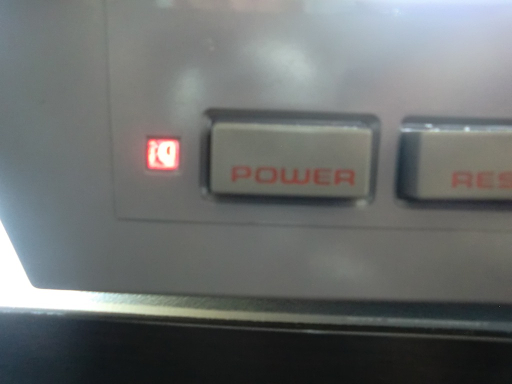
A quick test and the LED works! I did have to splice in a 10K resistor in the LED wiring. This should be visible on the white wire above, the resistor is mostly covered by heat shrink.
Some more testing using the USB hub to supply the power to the Raspberry Pi.
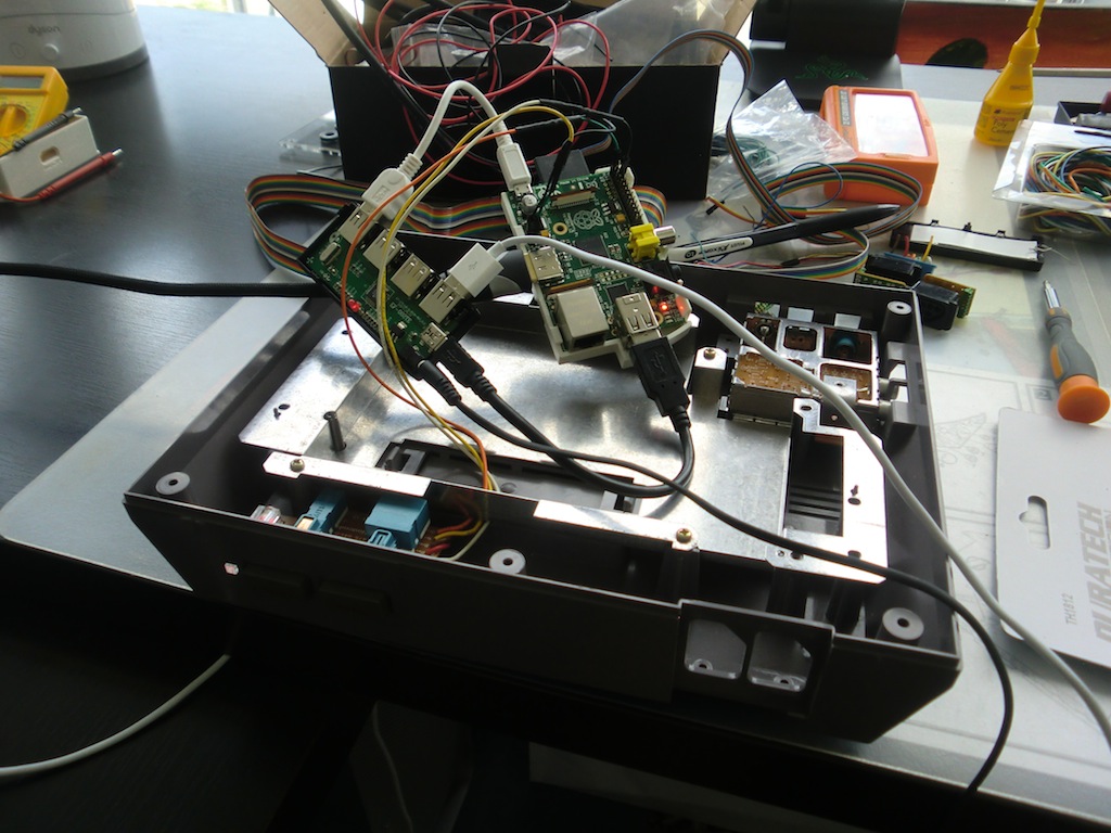
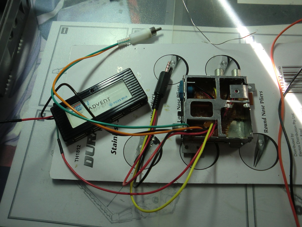
I took the USB hub out of its case and soldered in some wiring so it can be connected to the NES power port.
The rest of the external connectors are wired in.
I cut the positive (red) wire from the power port to the USB hub about half way and added the single pin Dupont connectors into it, this is where the power switch plugs in.
The wiring looks like this, the positive wire is basically spliced and the negative wire is left alone:
(+ wire from port)------[###]-----/pwr switch/----[###]------(usb hub)
|
(- wire from port)-------------------------------------------|
[###] = Dupont connector
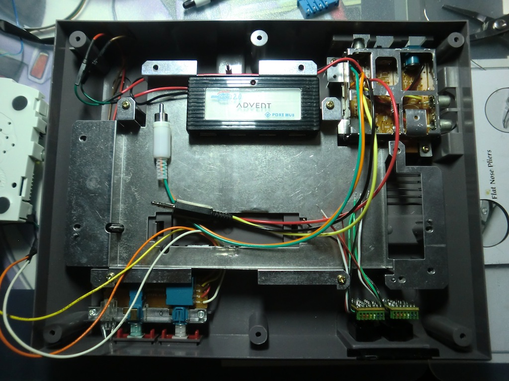
The USB hub, A/V block and the front panel all connected and in place.
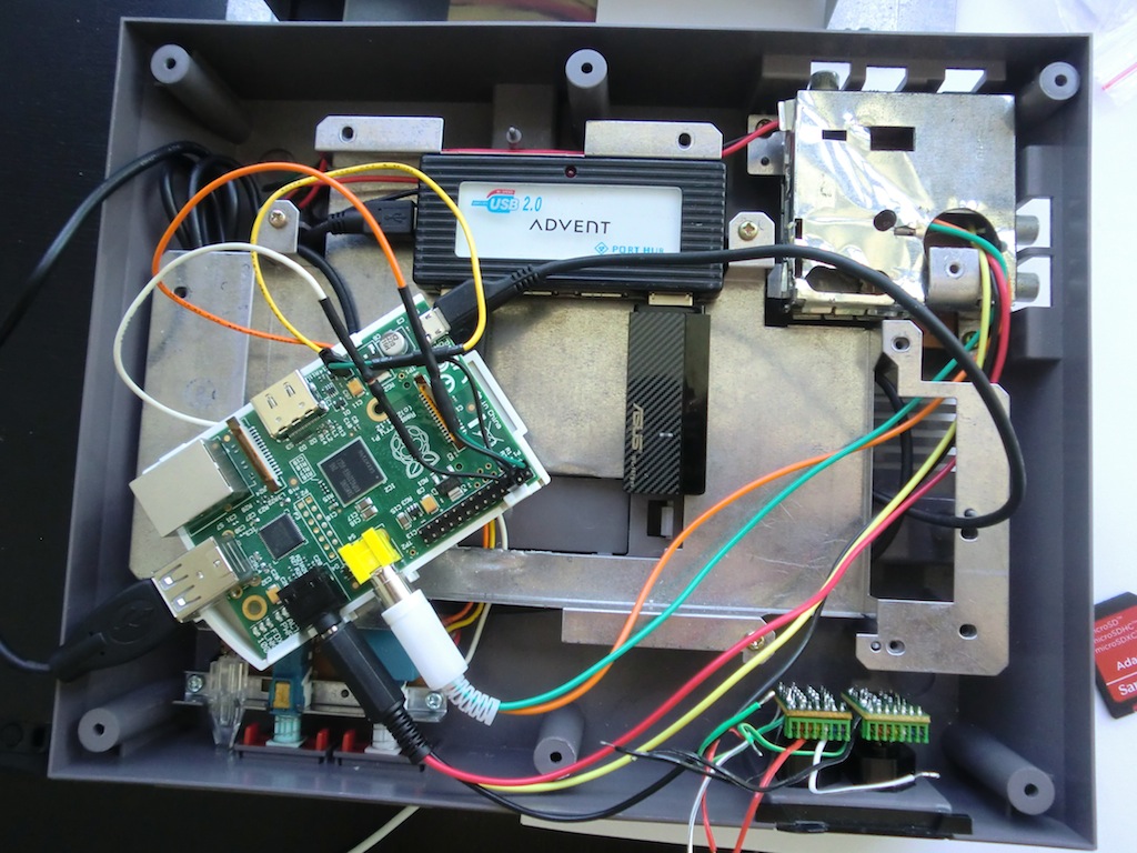
Testing the connections with the Raspberry Pi.
Continue reading the next part of this post: Raspberry Pi in a NES Case - Part 2 - Connecting the controllers and finishing up
-i
