A good soldering iron is needed to assemble this, something with temperature control is probably best. A clamp and magnifying glass can also be handy, I used the clamps to hold the PCB in place while soldering.
Here are some links that are useful:
PCB Holder with Magnifying Glass
48W Temperature Controlled Soldering Station
It took me around 4 hours to complete all of the soldering.
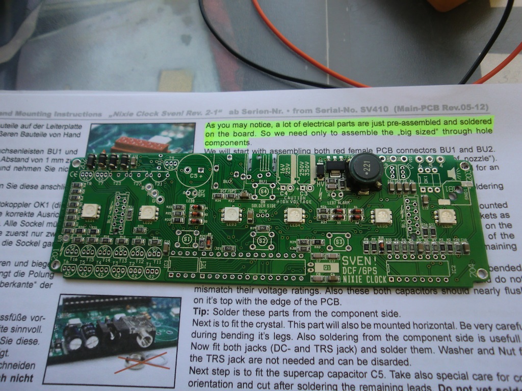
The main PCB has some components fitted to it already, only the large components have to be fitted yourself.
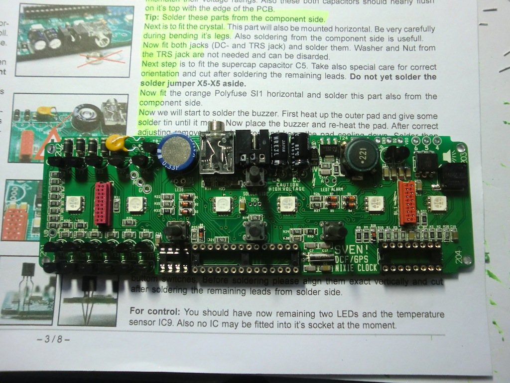
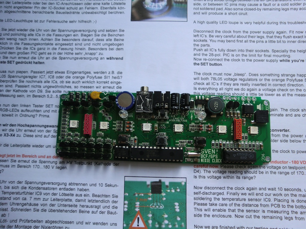
All of the main board components fitted.
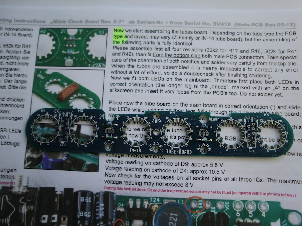
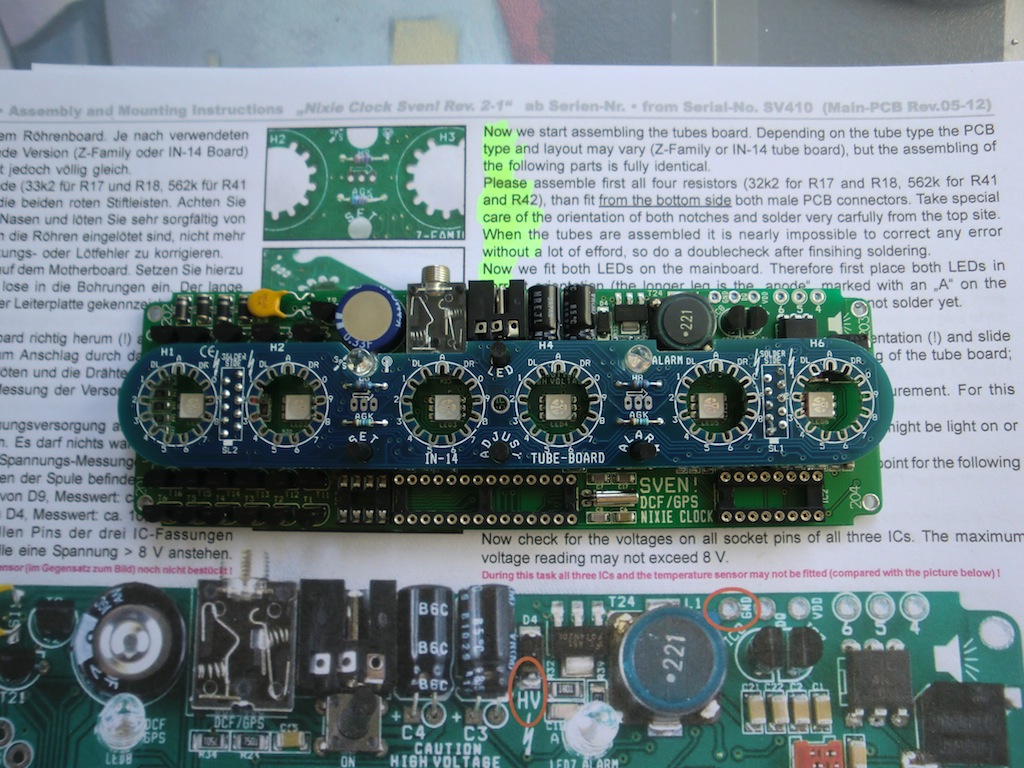
The tube board has components on both sides, the top is like this.
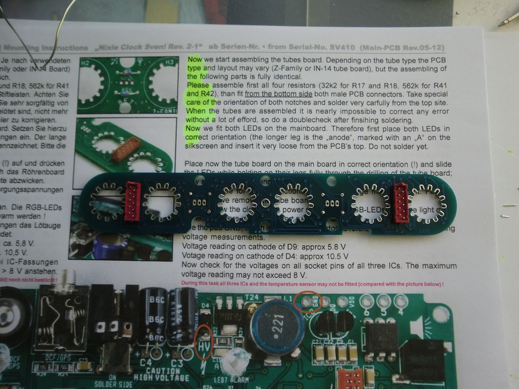
The bottom has the connectors to plug into the main board.
Test fitting the tube board on the main board and aligning the LEDs.
The ICs are fitted to the main board.
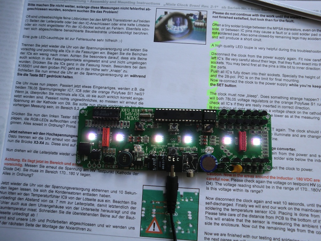
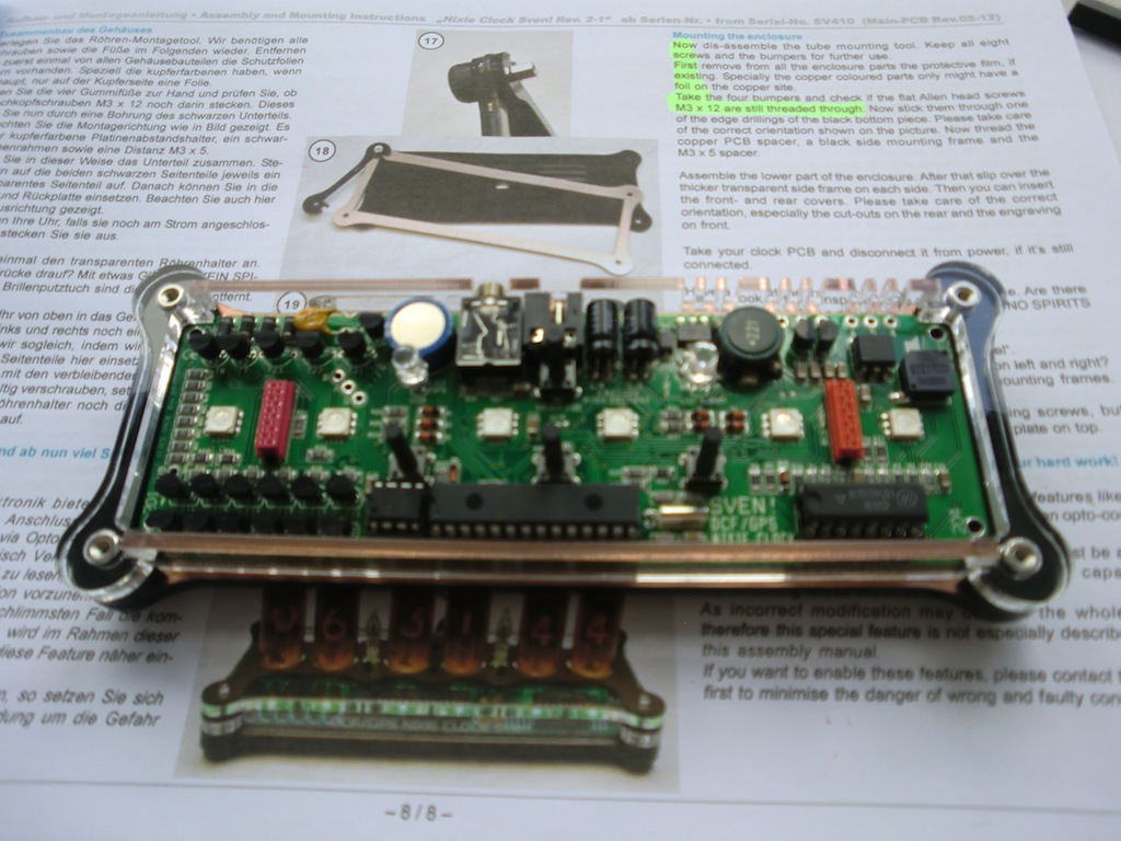
First functional test, it works!
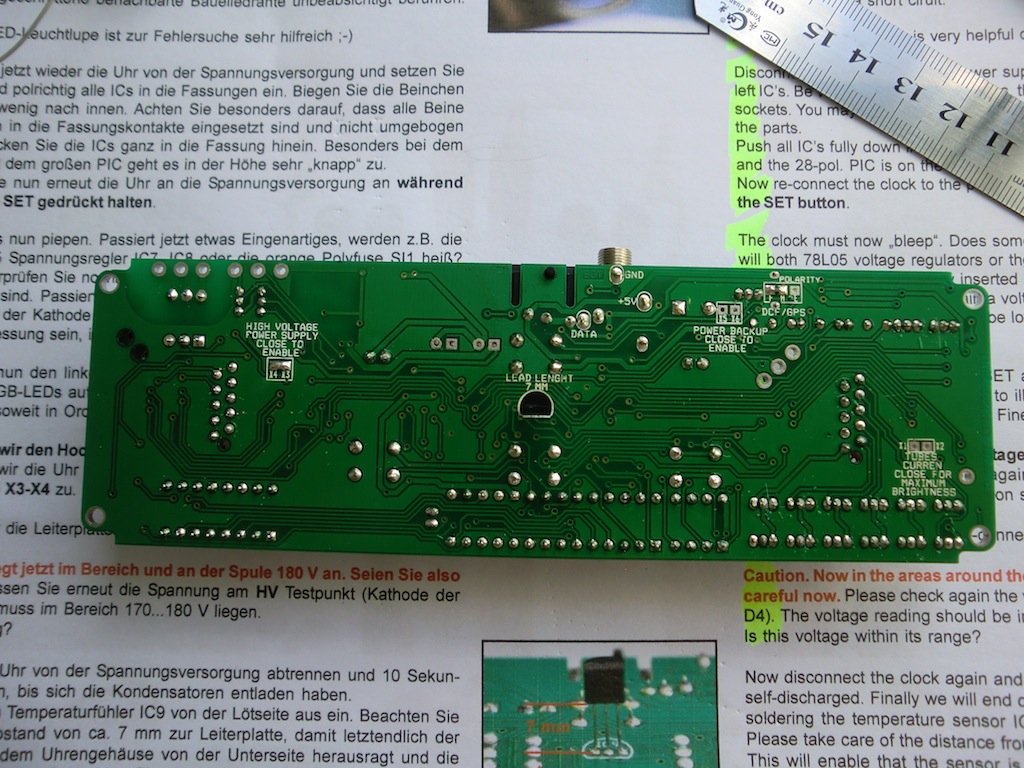
The heat sensor is soldered into the bottom of the main board.
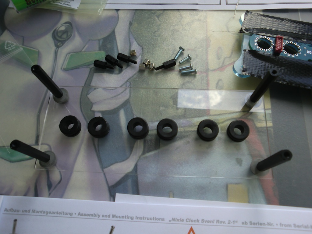
Assembling the tube holder.
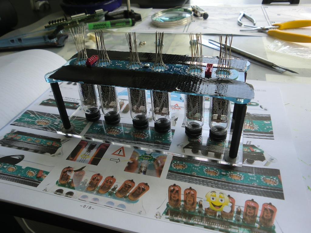
Tubes and tube board in place inside the tube holder.
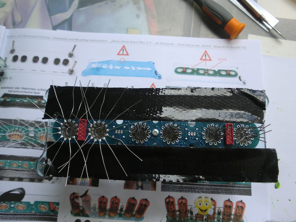
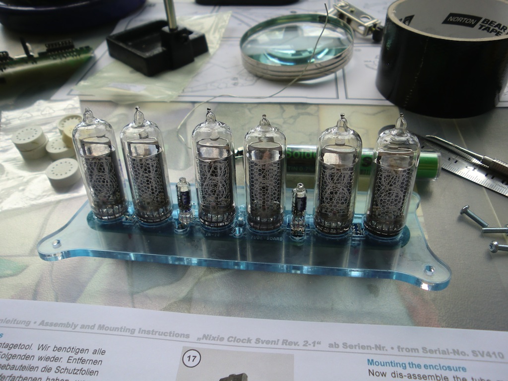
The tubes have a lot of pins, soldering them is quite tricky because they need to be lined up while you solder them in. For each of the tubes, I soldered a single pin in first, aligned the tube to sit straight and while having it in place soldered another pin on the opposite side of the tube. With the two pins soldered in the rest can be safely soldered without worrying about tube alignment.
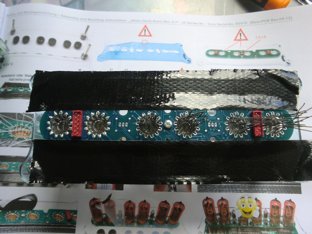
Completed tube assembly.
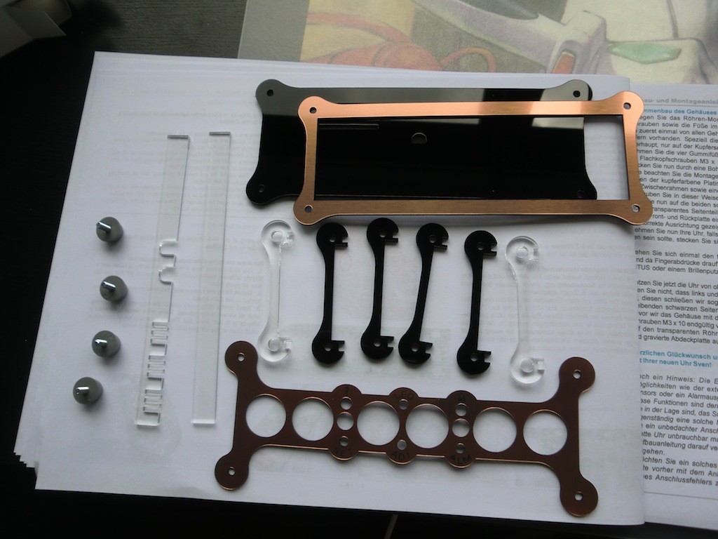
The clock housing comes in about a dozen pieces.
Once assembled, the main board drops right in perfectly.
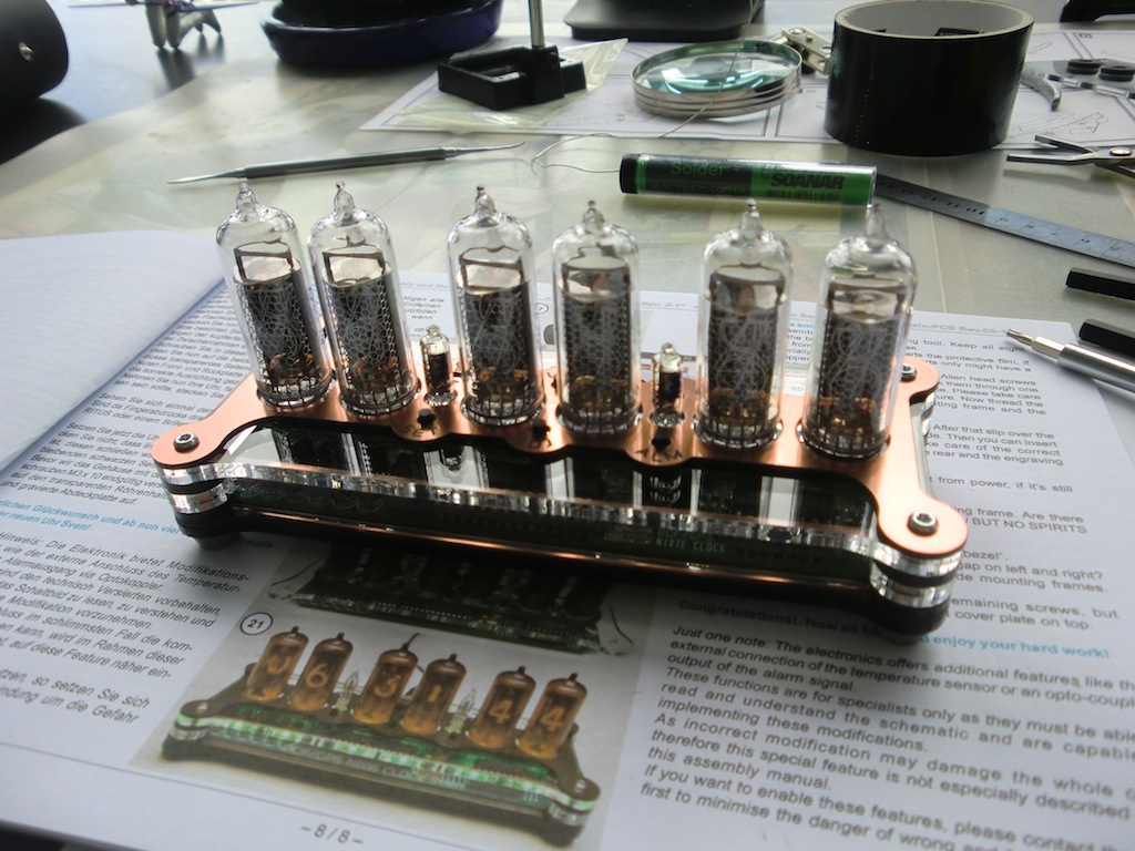
Everything screws together for the final finish.
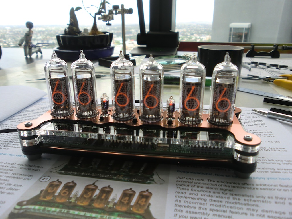
Testing the clock with a count down sequence.
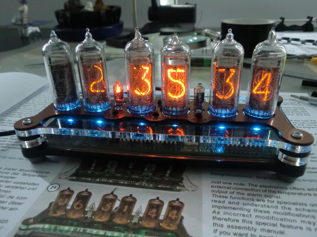
Some LED lighting turned on.
Unfortunately when I assembled my clock, everything worked except for the LED effects. When the 12f629 PIC was disconnected, the LEDs would light up, but obviously no effects would work. If the PIC was plugged in, the LEDs would not work.
It turned out that my PIC got erased in transit and needed to be reprogrammed. Lucky for me I found someone with a PIC programmer (thanks Steve!) and Mr Nixie (Jürgen) sent me the binary to transfer to the PIC.
Once the code was transferred over, the LEDs worked!
One thing I've noticed with the temperature sensor is that it doesn't seem to be very accurate, so I've disabled the temperature display on my clock.
Overall this was an awesome present and much fun to put together.
-i
