As a reference this is what my Portabee looked like prior to the rebuild.
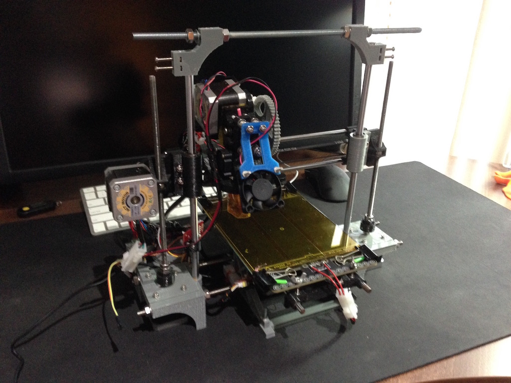
During the rebuild I've changed quite a few things, most of the changes were designed to make the printer easier to use and service. Some features were aimed directly at making the printer more stable.
As a summary, this is the list of improvements:
- New printer base, for printer stability and supporting the addition of a metal frame/cage around the z-axis
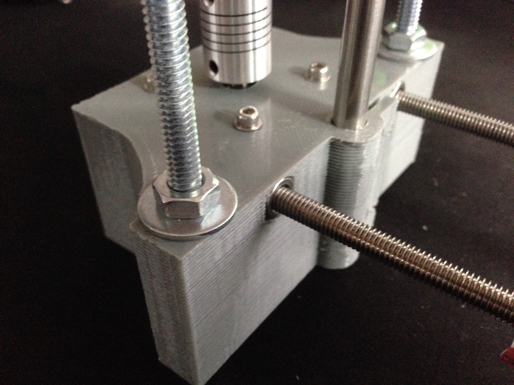
- Addition of motor couplers for the z-axis to prevent the z-axis from getting out of sync due to z-motor threads popping out
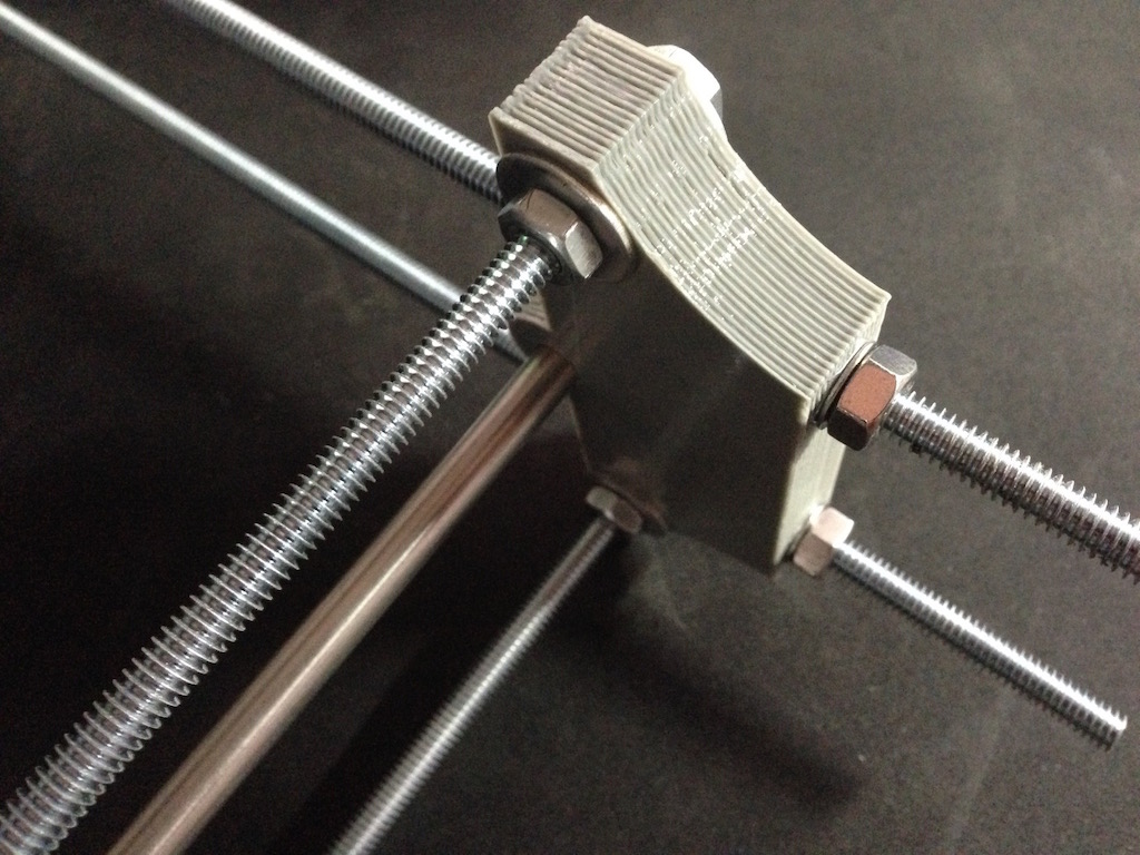
- Addition of springs for the heated platform support to allow easier adjustments
- Extended y-axis rods
- Additional plugs on all of the motors for easy disconnection
- Completely revamped central wiring
- Flipped around the heated platform 180 degrees for better cable management
That's quite a few differences to the original Portabee. To show these off I'm going to go through the photos I took during the various stages of this rebuild. At a later point I will make all of the source files for the new components available as well.
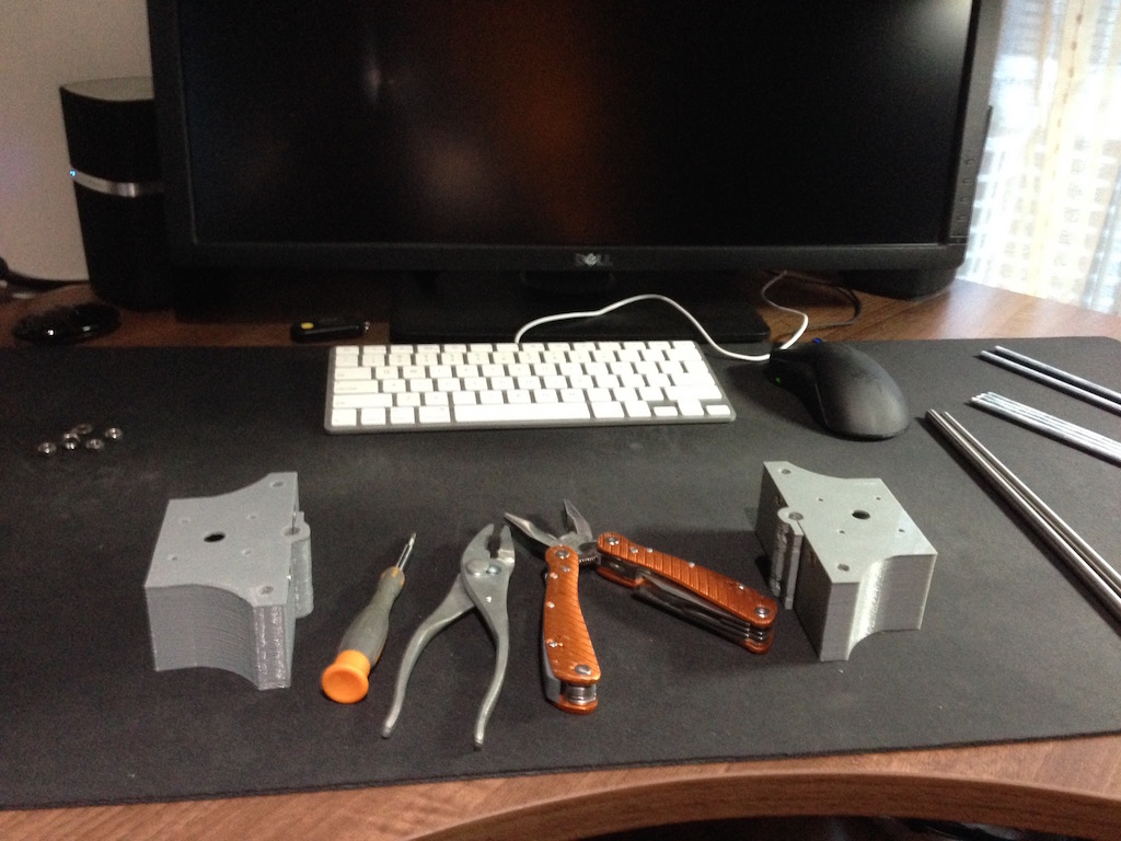
The first thing I had to do was order new 8mm and 6mm rods for the z- and y-axes respectively. These were easy to come by on eBay and didn't take long to arrive. I also bought additional threaded steel rods that will make up the frame around the z-axis, these were 1/4 inch threaded steel, which is not the same as the threaded rods used for the original Portabee.
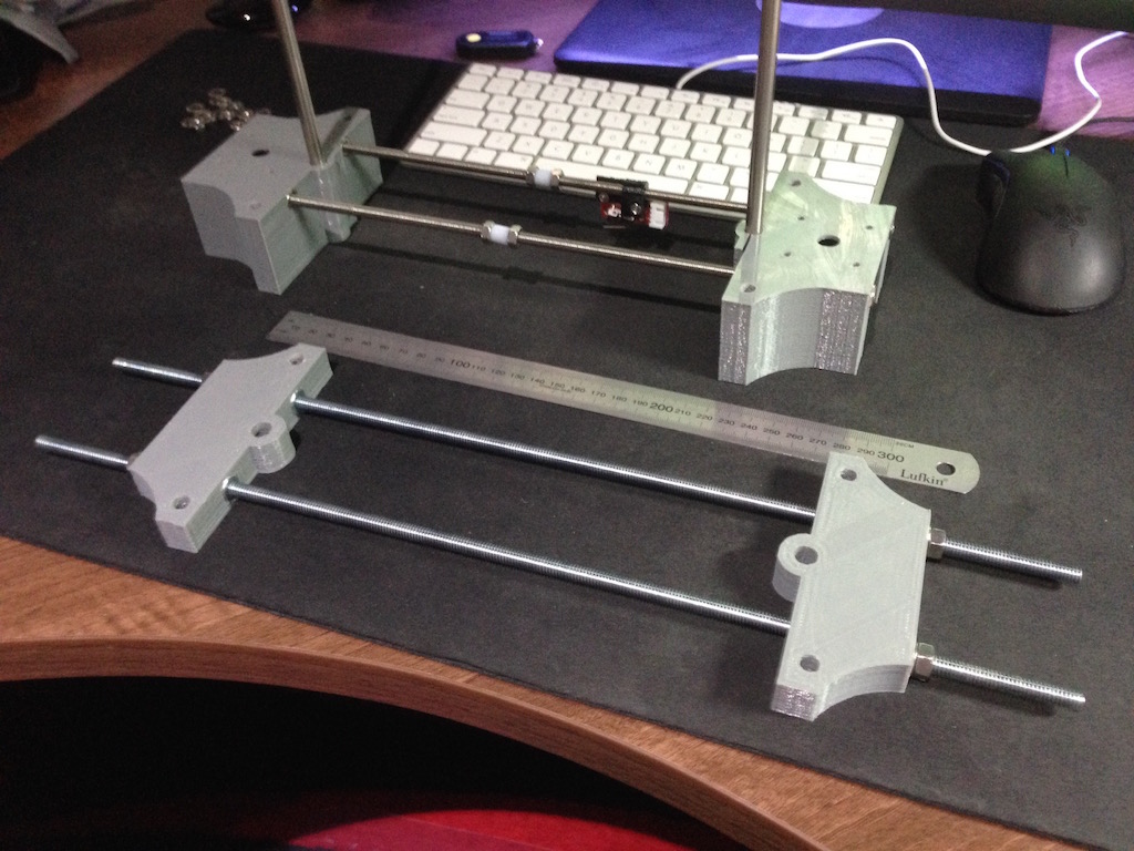
Prior to disassembling my Portabee, I used it to print all of the components that I would need in the rebuild. Luckily these were few, just the top and bottom parts of the printer base.
With the base components printed, I was ready to roll.
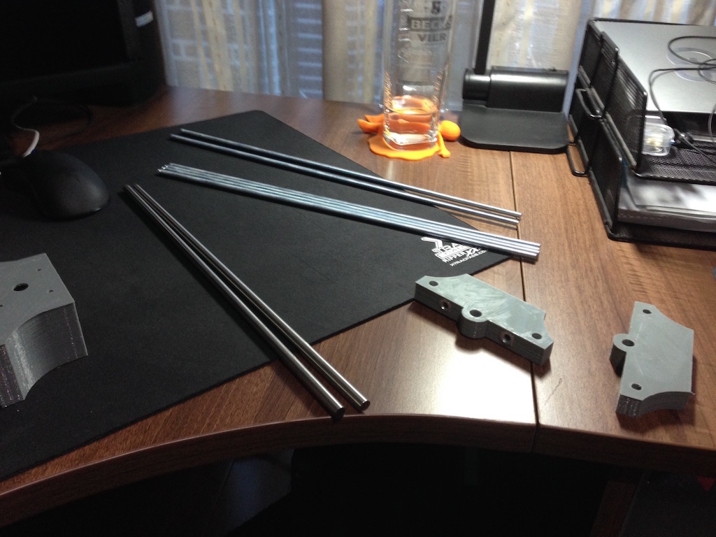
Since the original y-axis threaded rods were long enough, I used them in the new base. These had to be threaded all the way from the front to the back part of each base section since there is a nut on either end. A bit of a painful process, but this way I could be sure that each of the rods was aligned properly.
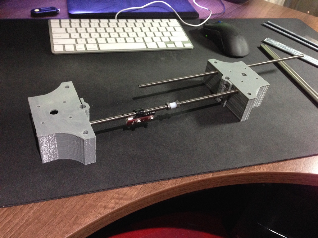
The top part of the base was put together with the 1/4 inch threaded rods and aligned to the measurements of the bottom part.
At this point I could put the top and bottom base parts together using the 1/4 inch vertical rods.
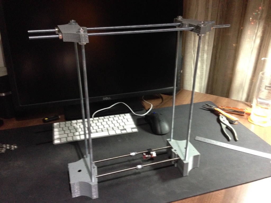
At first I didn't use washers when securing the nuts, I found this was less than desirable with the whole frame being wonky, so I took it apart and added nuts and tightened everything properly. The result was a nice solid frame.
That covers the z-axis cage/frame. In the next part I'll describe the changes I've done to the motor housing, the motor couplers and heated platform support improvements.
The second part is now posted, you can read it here: http://www.igorkromin.net/index.php/2015/03/04/rebuilding-the-portabee-3d-printer-part-2/.
-i
