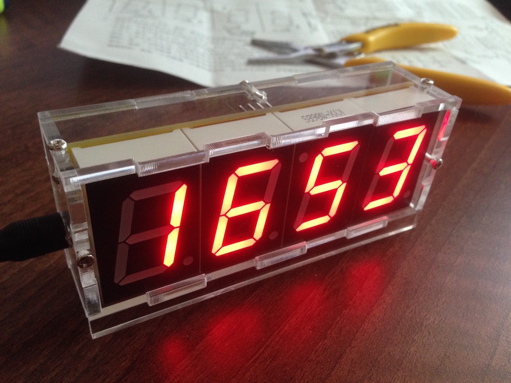
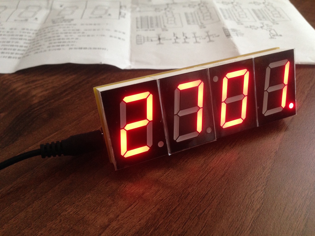
This is the end result for the clock that I've put together. Stay on for step-by-step instructions further down.
Can't wait to see all the photos?
♣ Open image gallery
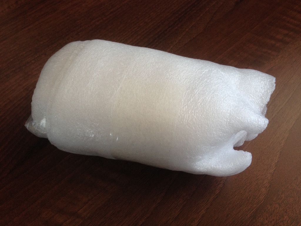
for this post.I ordered two kits, one red and one blue. They came nicely packaged in soft foam wrapping.
Unfortunately I received only one case (I ordered two). The missing case is being sent to me however.
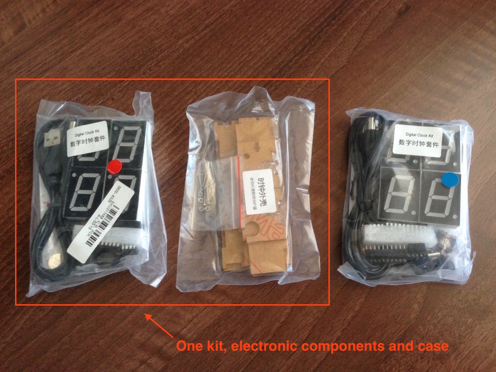
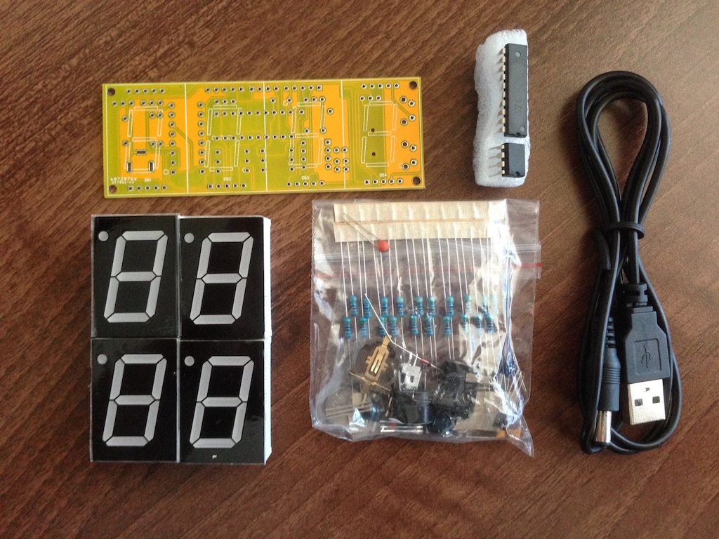
So lets see what's in the kit. There are instructions (in Chinese I presume - not a word of English), circuit boards, all the electronic components, ICs, the LED displays and the USB cable for power. This is put together quite nicely. The circuit board is of great quality too.
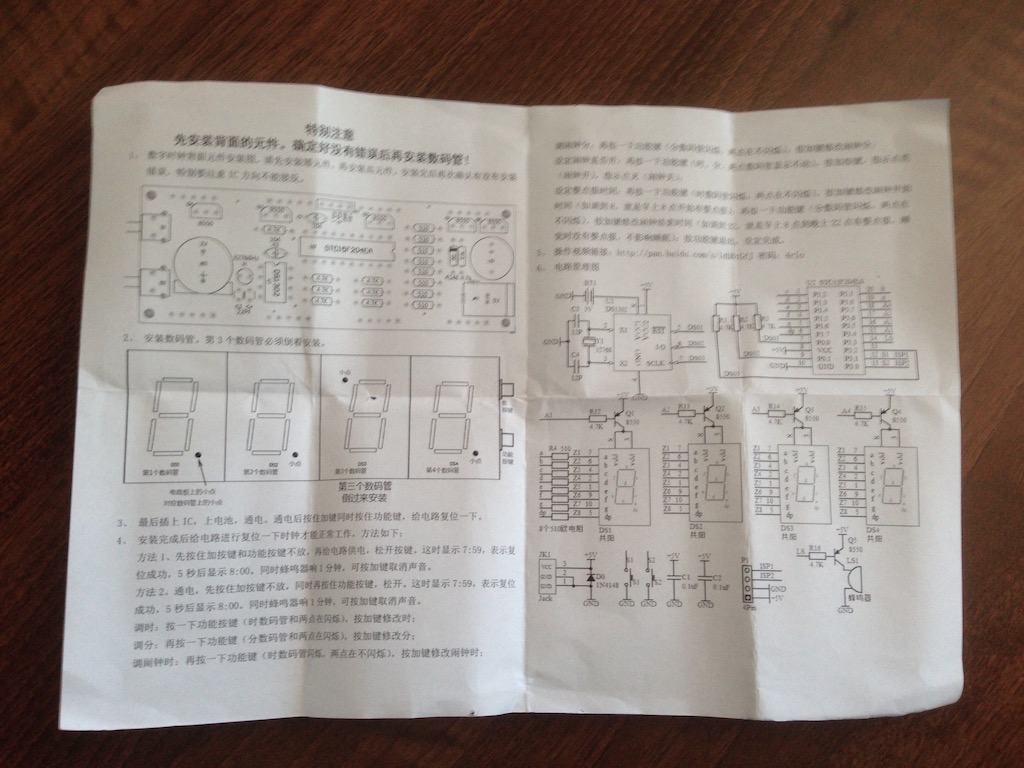
Since the instructions were more or less useless to me, I just followed some common sense when soldering everything in place. This is the order of components that I soldered on (these are numbered in the instruction drawing)...
Soldering order
4.7k - R1, R2, R3, R12, R14, R15, R16, R17,
510 - R4 - R11
D0
Q5, Q4, Q3, Q2, Q1
C1, C2, C3, C4
P1
U1, U2
LS1, JK1, S1, S2, BT1
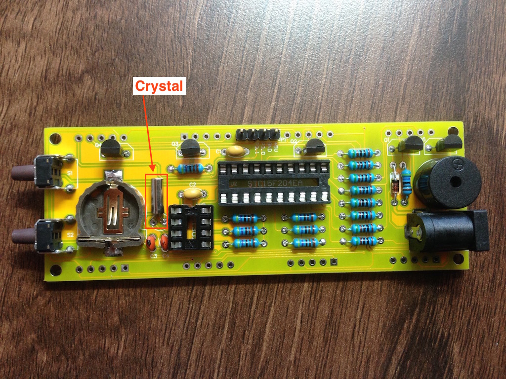
Y1
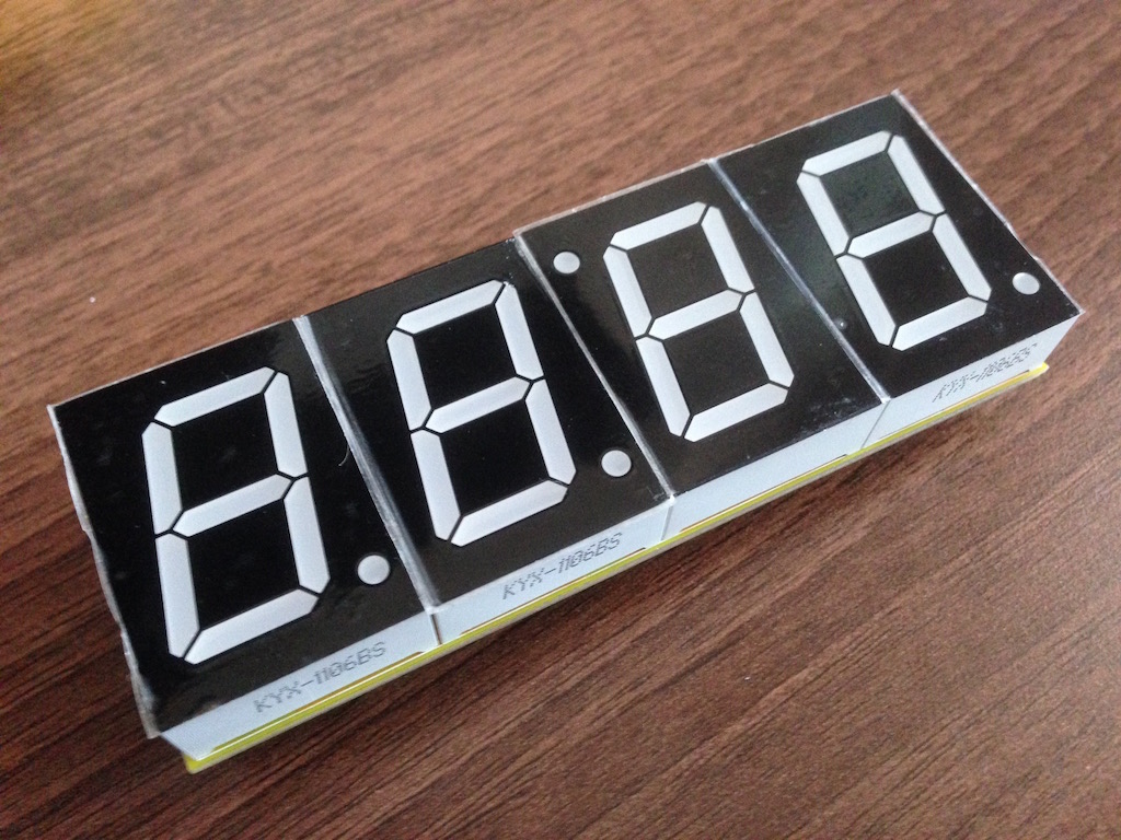
DS1 - DS4
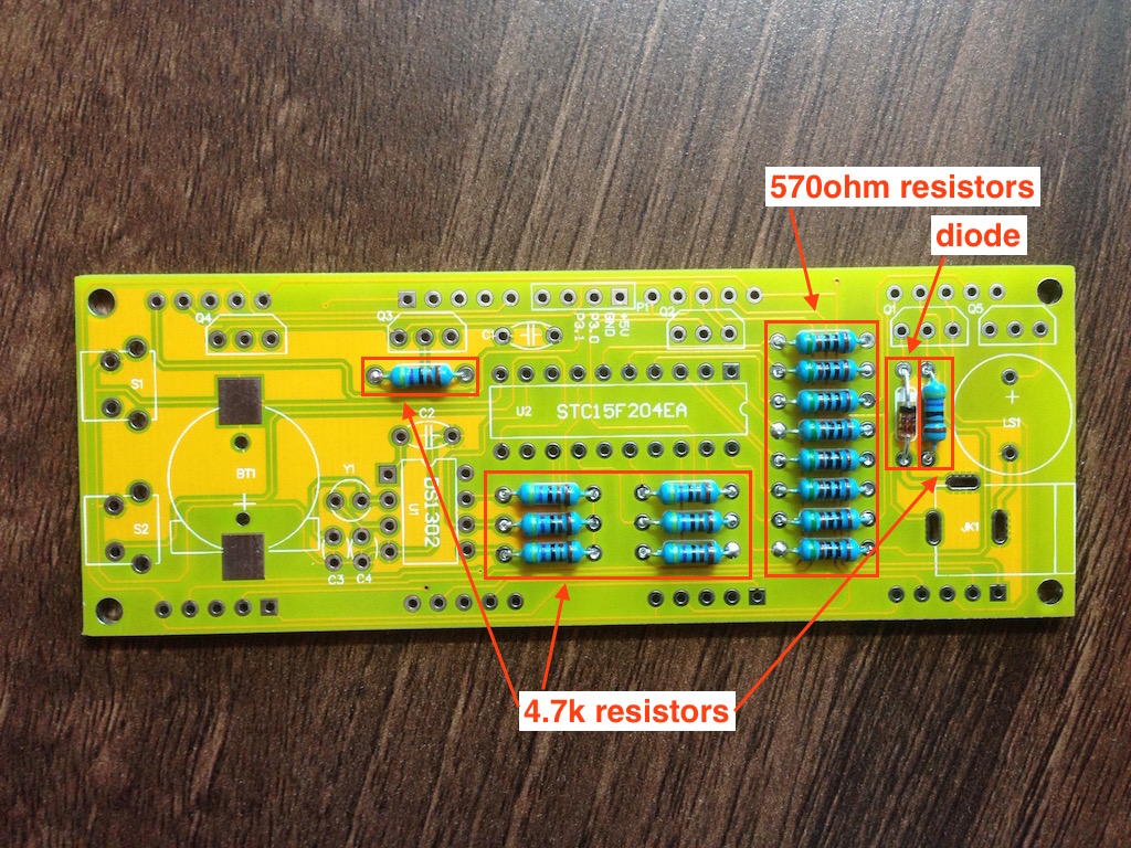
So lets see these in pictures...the resistors and the diode were in first.
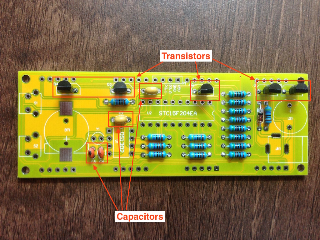
Transistors and capacitors were in next.
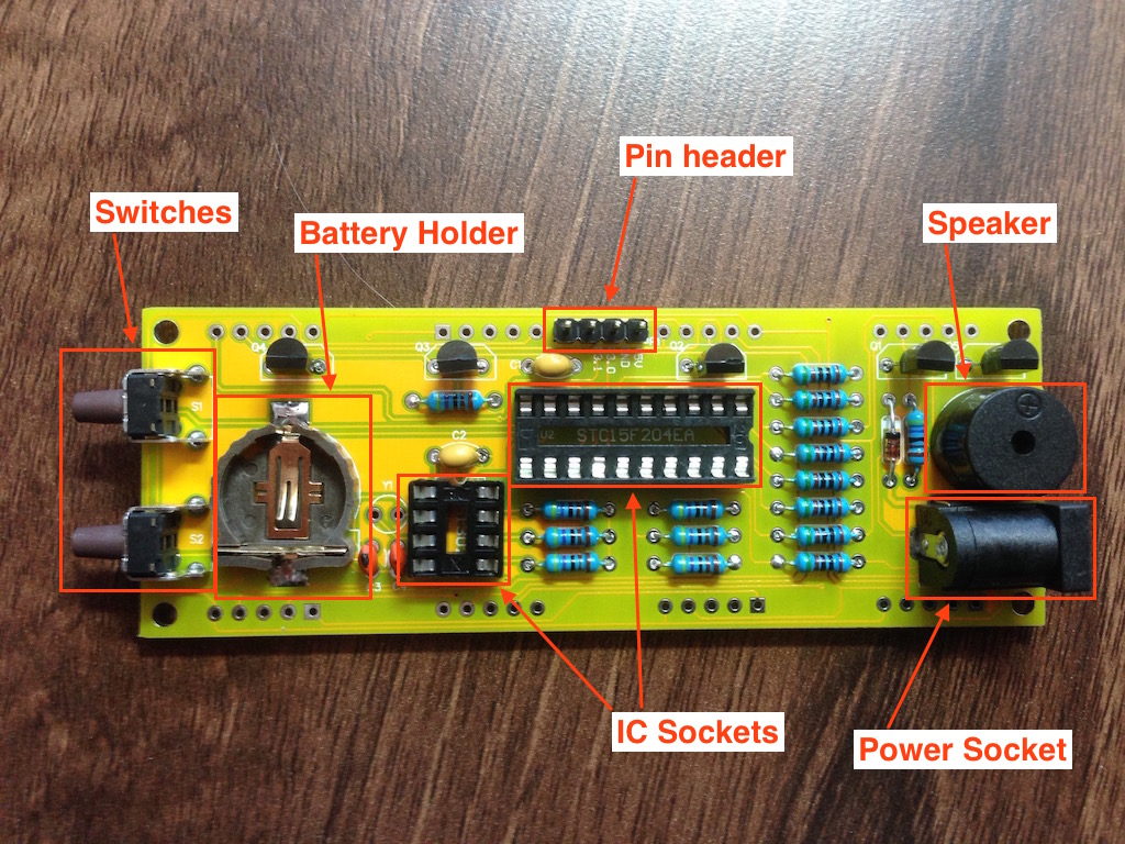
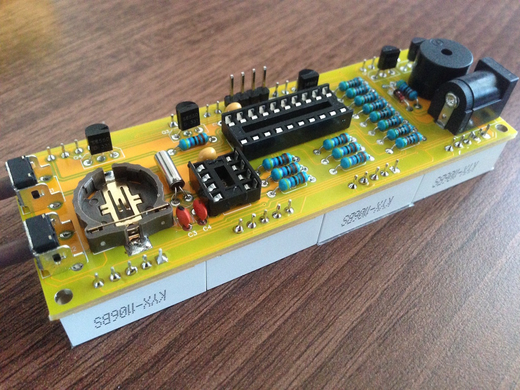
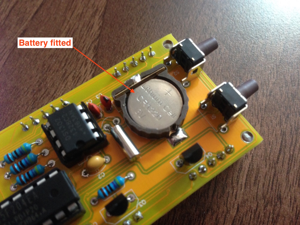
After this the switches, battery holder, IC sockets, pin header, speaker and power socket went in.
The crystal went in last, though I should have probably soldered it in while doing the resistors. With the battery holder in place at this point, it was a bit difficult to get it in place.
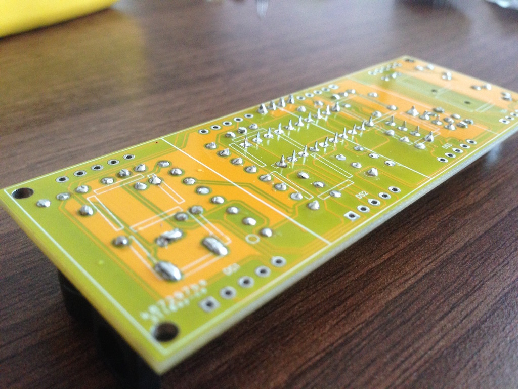
I was a little worried about the LED displays fitting properly so I made sure to cut down the legs of all the components as close to the board as I could. This is needed because the LED displays are soldered over the top of the legs of other components, on the opposite side of the board.
Then, making sure that the displays fitted flat and were aligned, I soldered each one in. I soldered pins on a diagonal of each display first, then soldered the rest of the pins. This made it easier to keep the displays aligned while soldering and gave some room for adjustments.
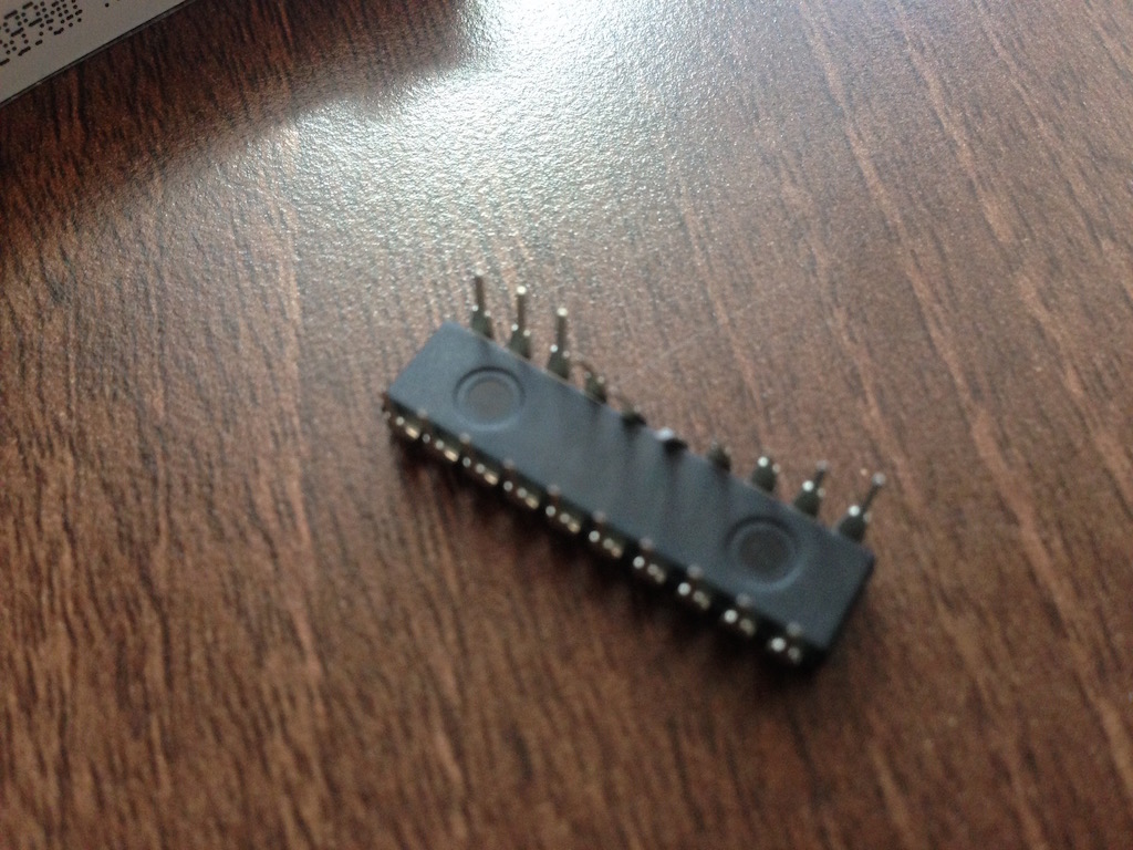
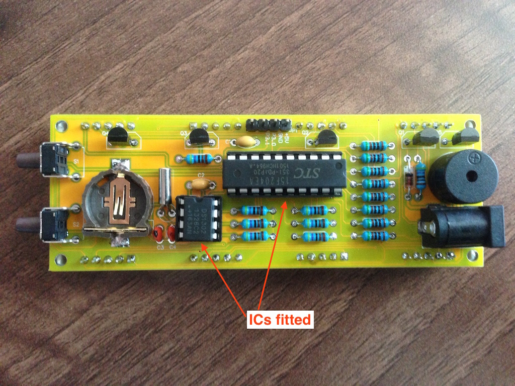
Now it was time to fit the ICs. The pins on one of mine were quite bent out of shape, but nothing a pair of pliers couldn't fix.
Finally it was the moment of truth! Plugging it in. All the displays lit up first time! At this point, I put the battery in too. The display didn't show anything resembling time however, I had to fumble with the buttons to work out how to set the time, this wasn't hard, one button selects the fragment to change (minutes/hours/alarm state) and the other button adjusts it.
Once the time was all set, I've started to put the case together. The assembly is more or less obvious. I really like how the nuts fit into the grooves and the bolts come down through perpendicular acrylic sheets to secure in place. Nice design.

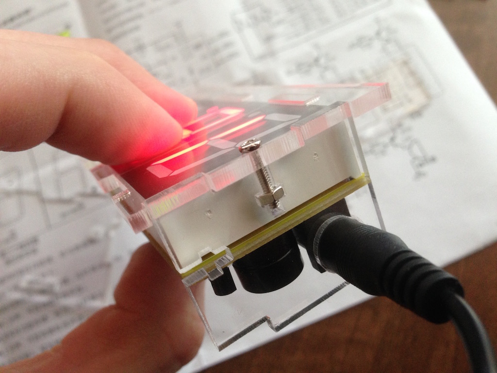
That's all there is to it!
Oh I did have some left-over components...
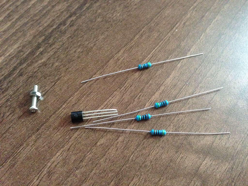
I was wondering what that pin header was for so looked this up. One of the ICs is a STC15F204EA microprocessor, so it's actually programmable and that's what the pins do, you can write your own code and upload it to the clock. Unfortunately the kit doesn't come with the code that's there out of the box.
♣ Open image gallery
for this post.Good luck putting together your own!
-i
