There is a version of this kit that does not include SMD components if you do not have the right equipment to work with those.
If you don't want to read the article, you can
♣ Open image gallery
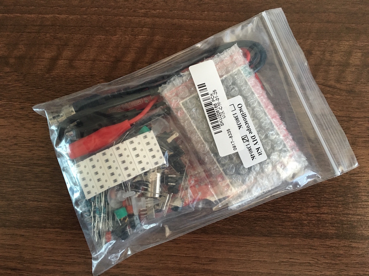
instead.So lets see what was in the kit...
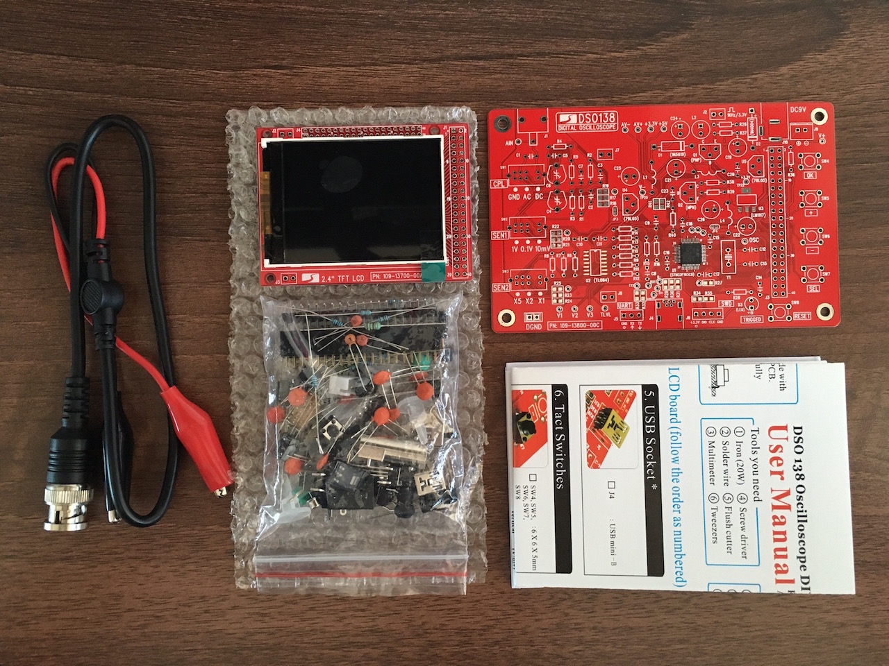
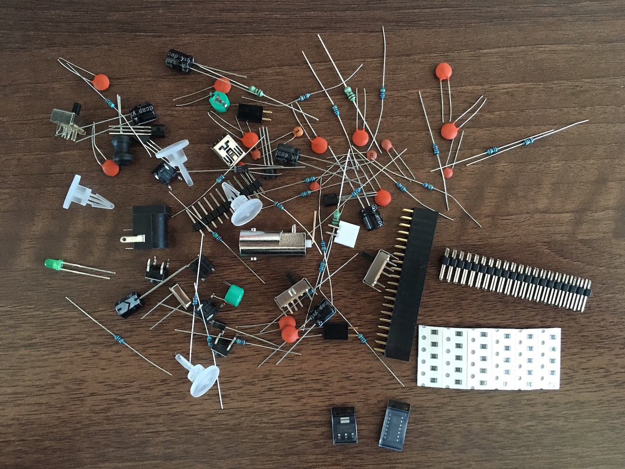
What I didn't quite like was that the components like resistors weren't marked with numeric values and I had to measure the values of each one. The same value components weren't put together on strips either, except for the SMD components.
The instructions were quite clear and printed on high quality paper. The only thing missing were instructions on how to solder on the SMD components. It's like the provided instructions started at the point where all the SMD components were already attached.
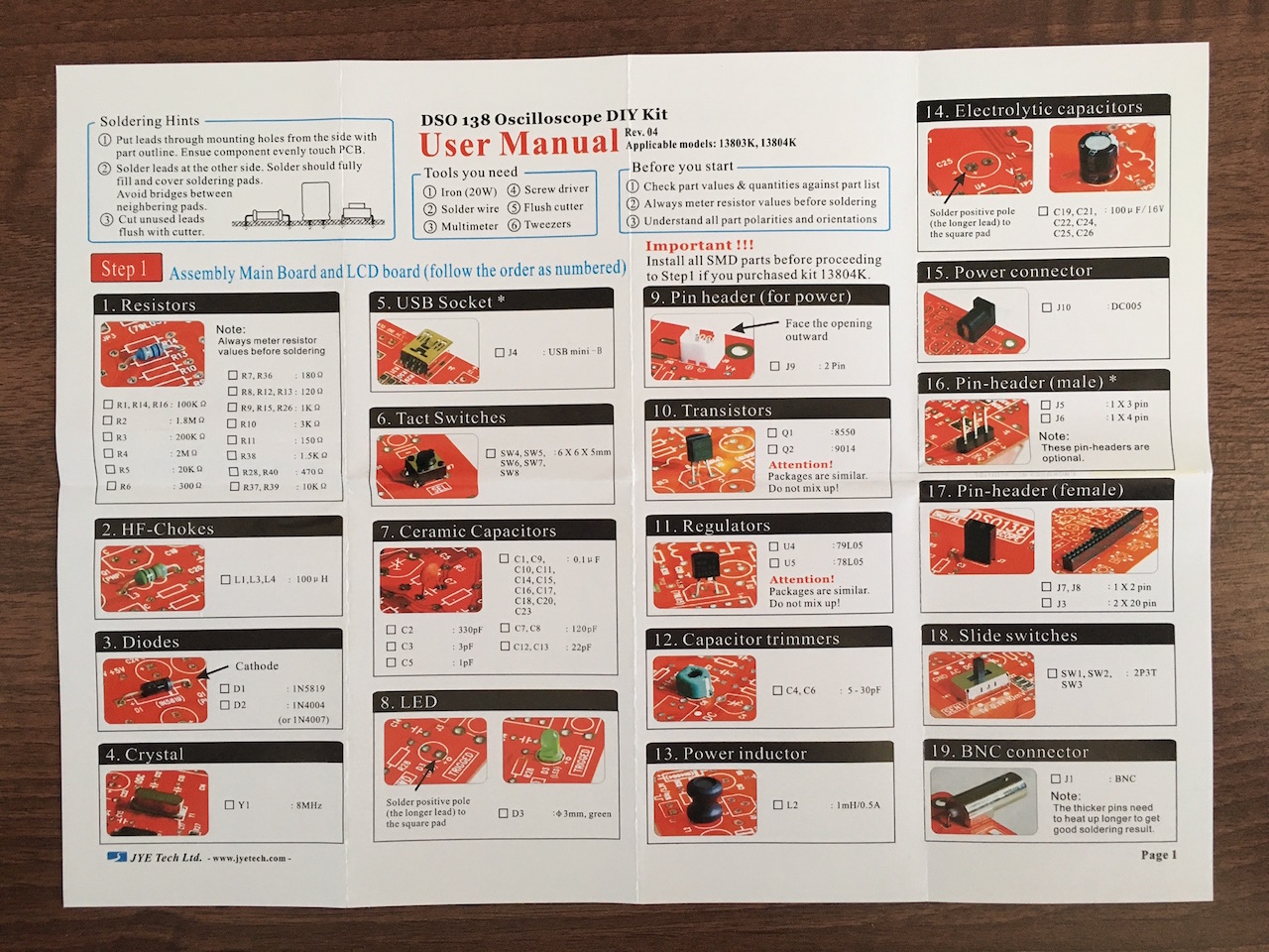
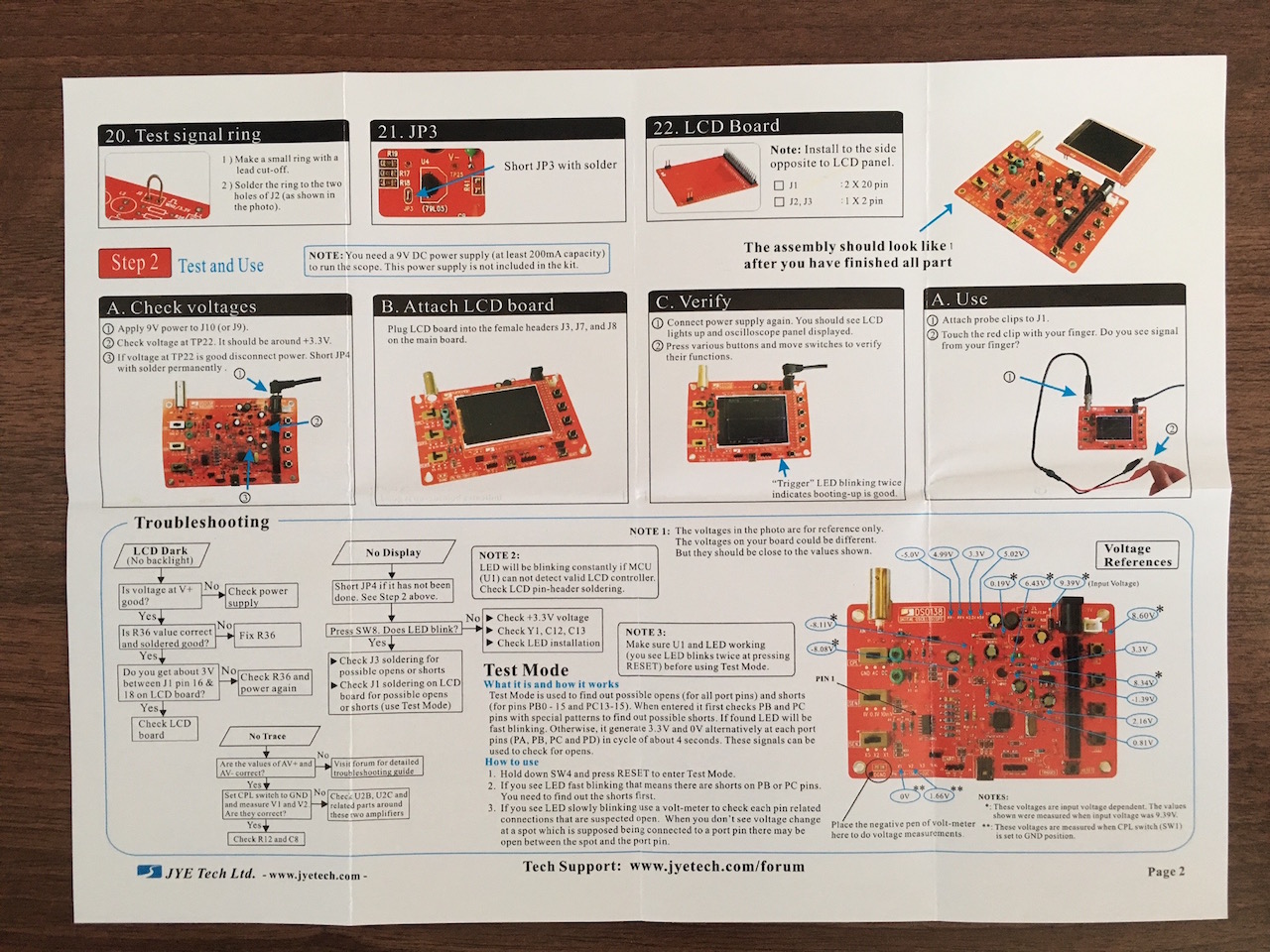
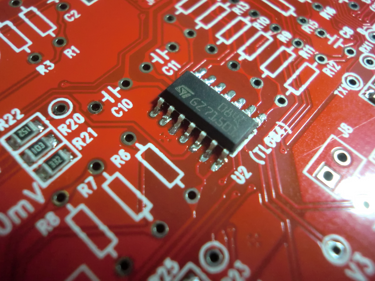
I won't talk about soldering on all the standard components as the provided instructions do that already. So lets look at the SMD soldering. The order of components soldered on doesn't really matter, I went with resistors, then the voltage regulator, and finally the IC.
The principle is always the same. Apply a bit of soldering paste to the PCB's pads, use tweezers to roughly align your components to the pads, then using a heat gun heat up some of the area around the component, then the pads around the component itself. You don't have to be too precise as the solder will flow into place on its own and the components will usually align without additional nudging.
Here are some images that demonstrate this...

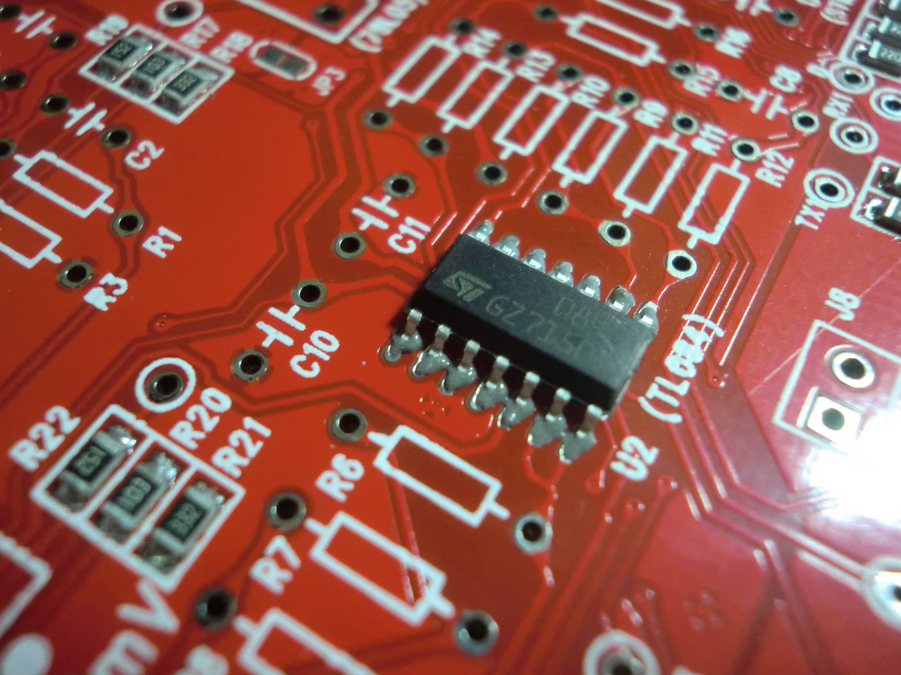
...and after heating...you can see that the solder has flowed to each of the pads and attached the IC to the board...
Here's a video that shows some of the earlier SMD components being soldered on...
Once all the SMD components are soldered on, this is the end result:
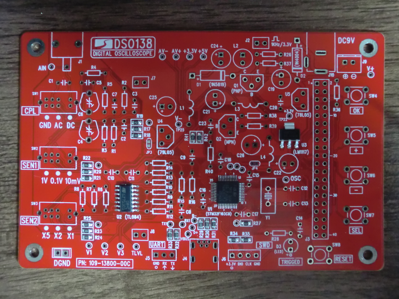
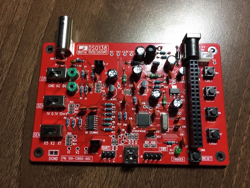
After getting all the standard components into place, we have something resembling the final result.
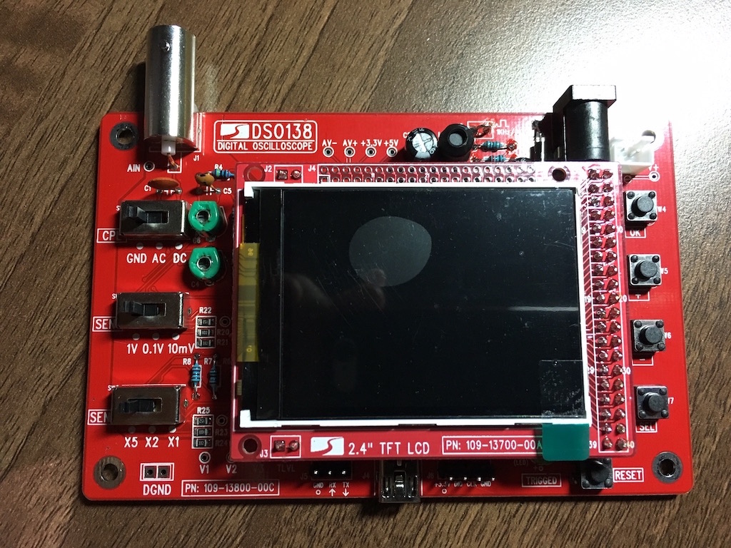
In my rush to get the LCD on, I forgot to short out JP4 and so when I turned the power on, all I got was a blank screen.
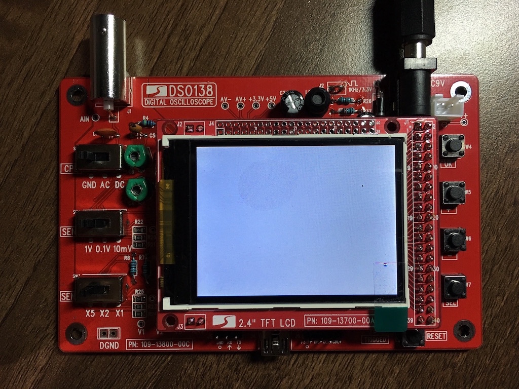
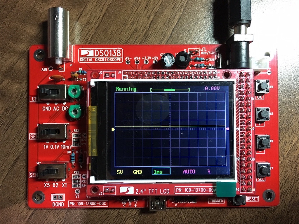
After removing the LCD, shorting out JP4, reattaching the LCD and turning power on it all worked!
The only thing missing now is a case, but I will have that covered soon - planning to make one with my laser cutter.
-i
