Spoiler alert - there was no gravity sensor! It was just a mercury switch. Boo! Besides that though, for the purpose of practicing SMD soldering this kit was fantastic! Virtually every component except the mercury switch and the power cable could be soldering on using soldering paste and a hot air soldering station, which was what I used.
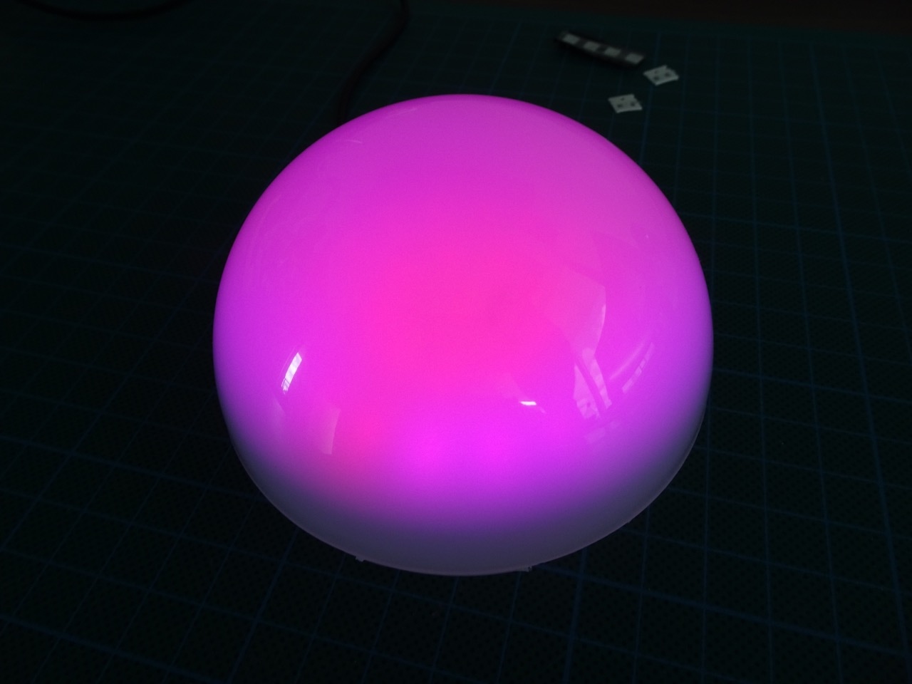
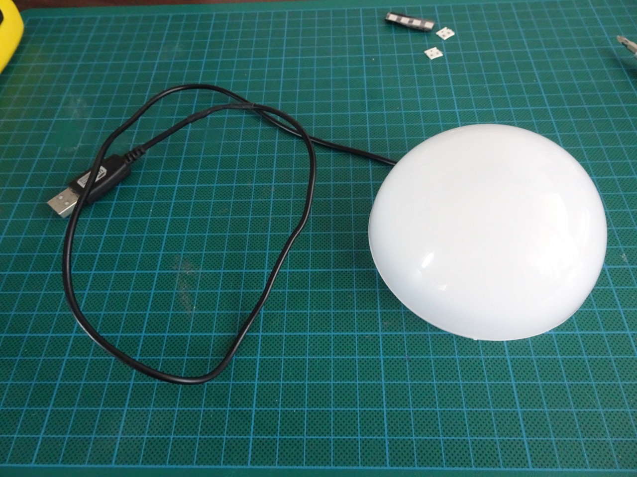
The end result looked very cool. The lights changed and spun around and throbbed and fluctuated, there were many cool effects. More on this later though.
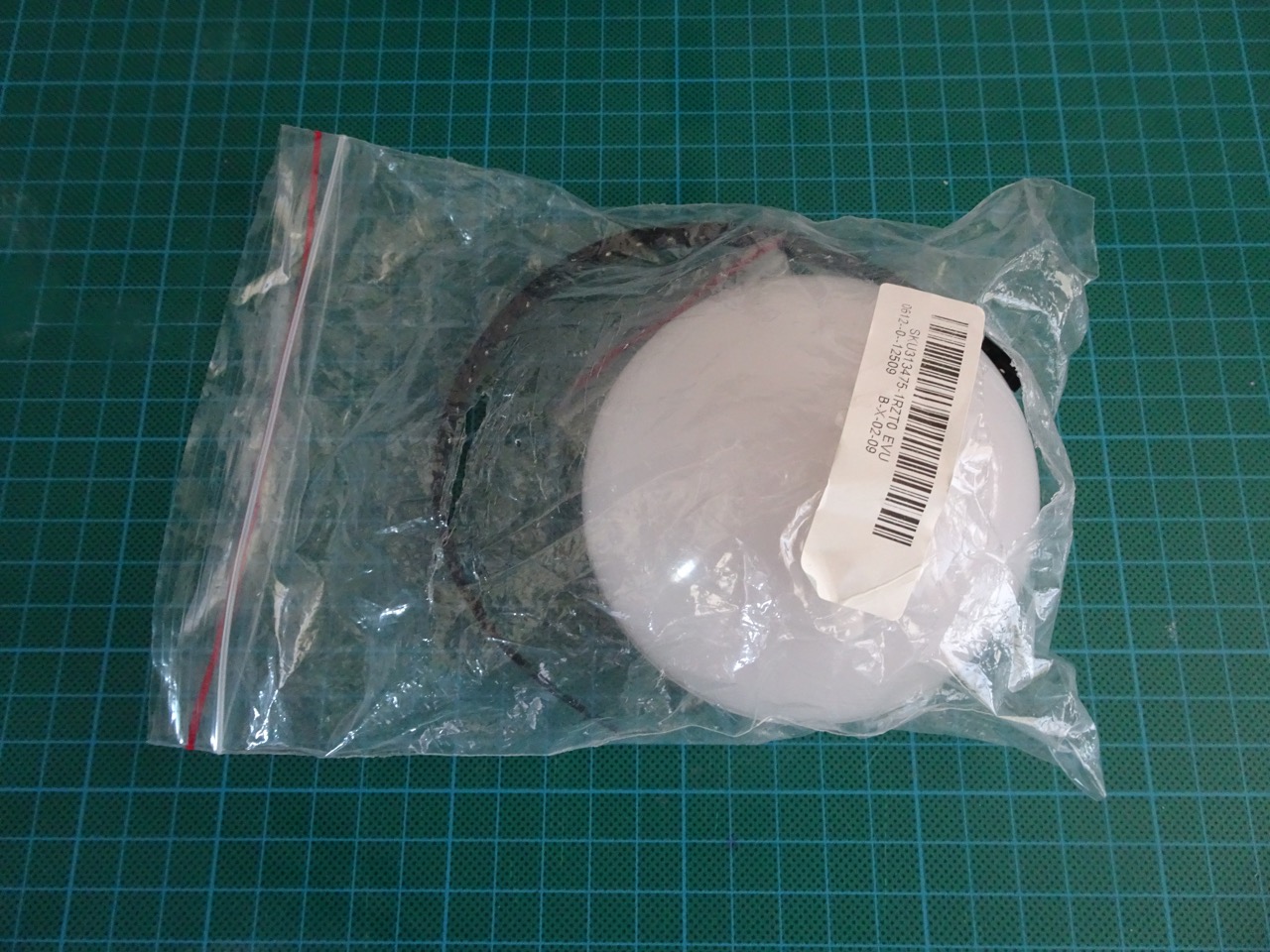
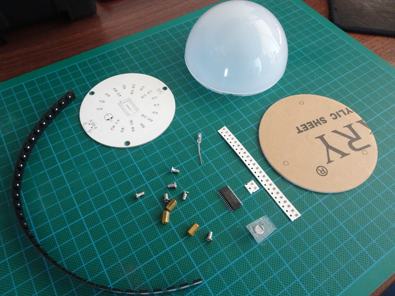
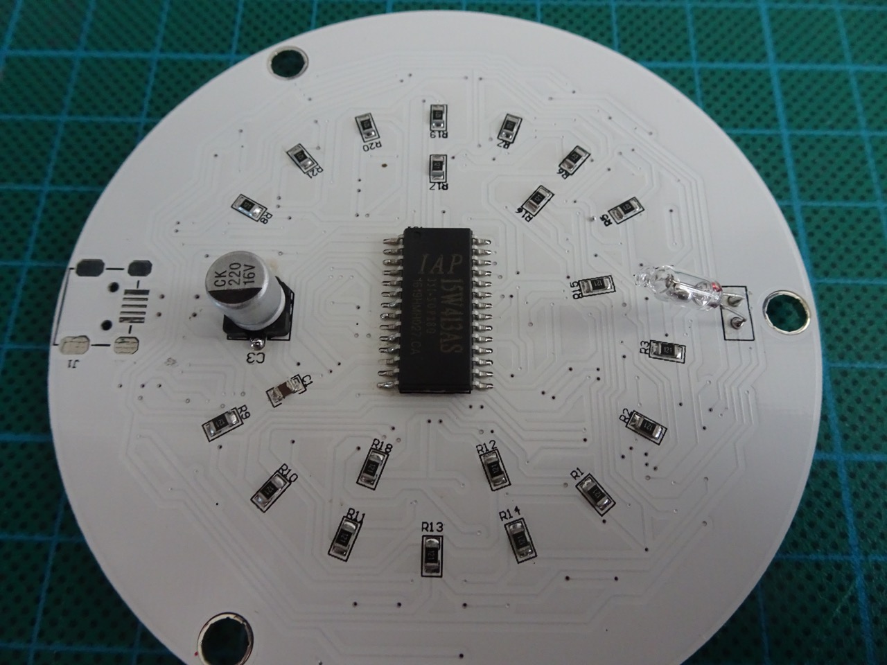
The kit came in a zip lock bag. Mine had a rip in it but no components (except maybe the USB cable) were missing. I did have to cut up one of my spare USB cables to use to power this kit. Most of the components were of the SMD type - RGB LEDs, resistors, capacitor and MCU. There were a couple of larger components including a metal cap capacitor and a mercury switch which was a through-hole mount. The PCB was white, which added to the look (and I guess reflectivity of the light). The housing was made up of a plastic dome and an acrylic base.
There was an assembly manual for this kit but I didn't really find it all that useful. The manual showed assembly using a standard soldering iron. I used soldering paste and a heat gun to mount most of the components.
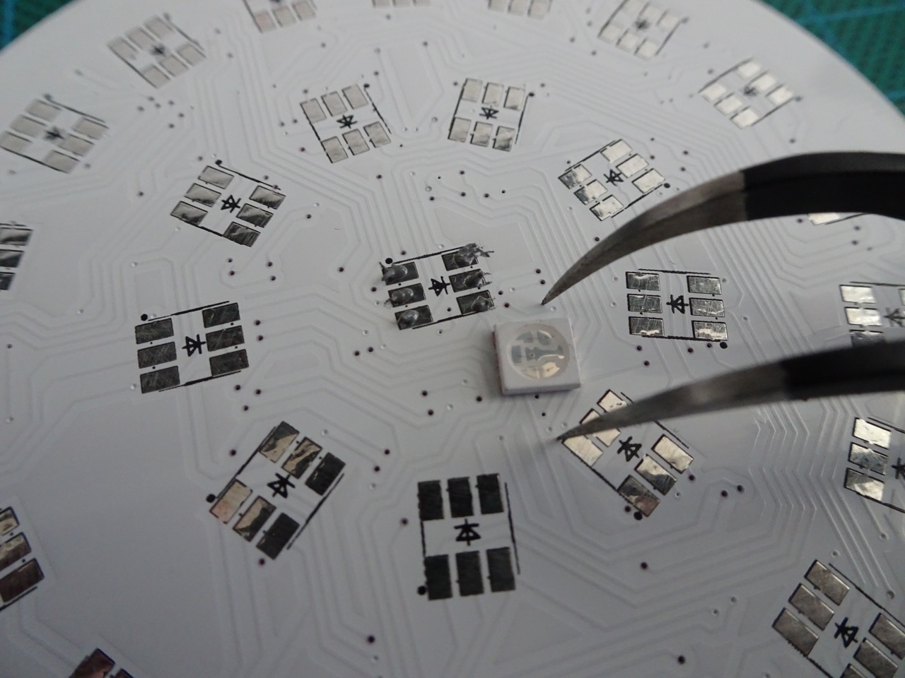
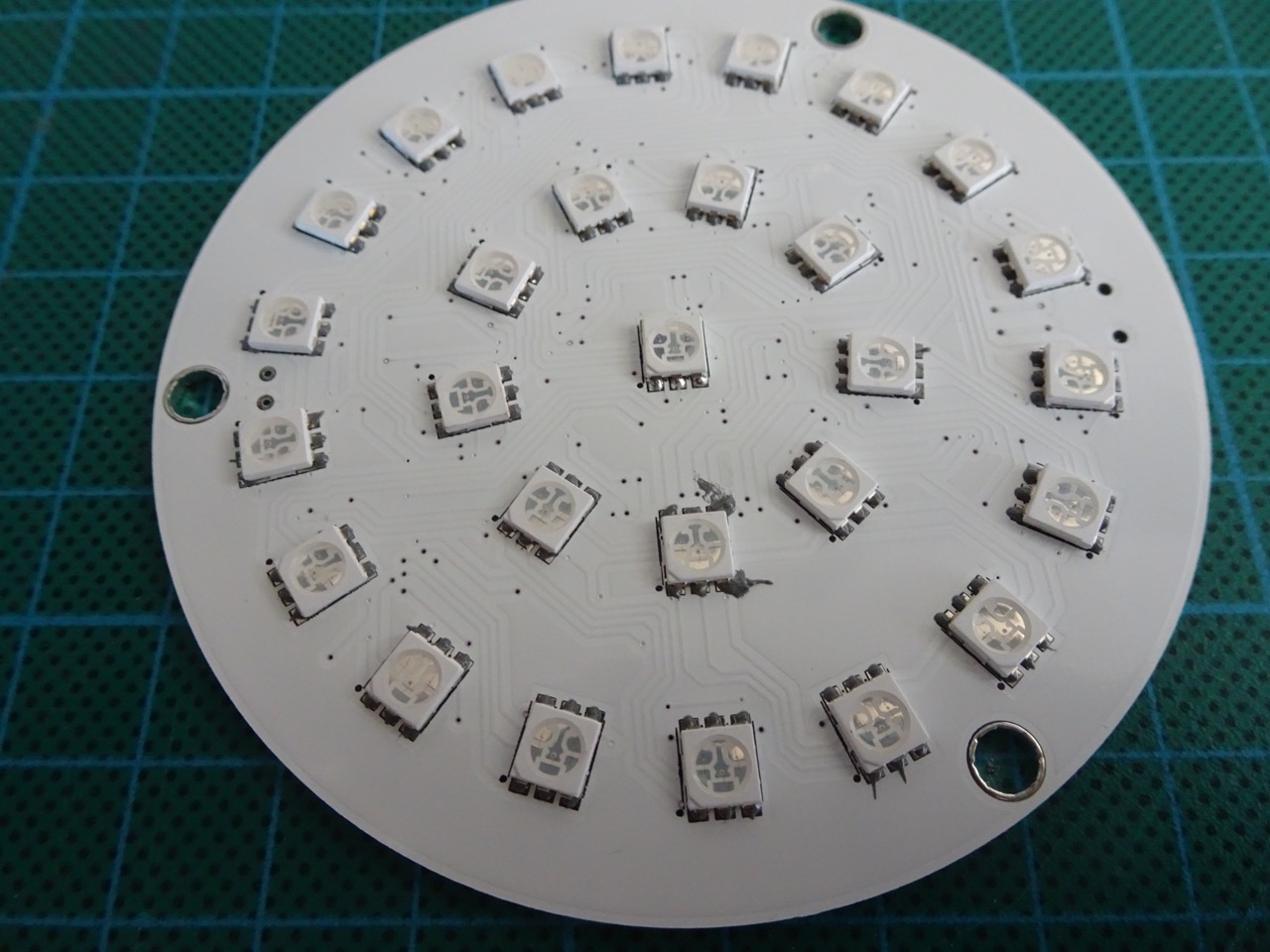
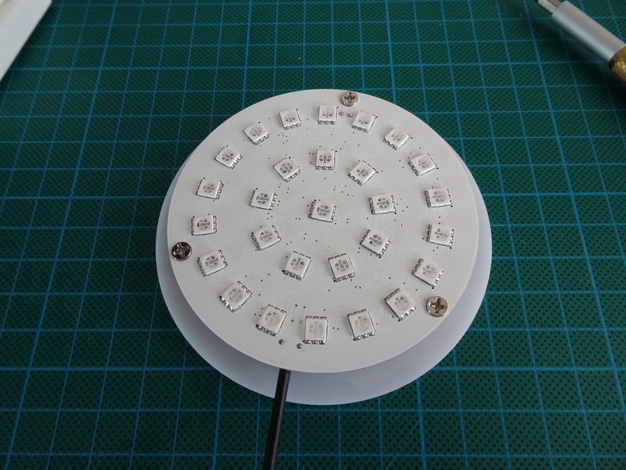
My starting point was with the RGB LEDs. To get these in the right position, I had to line up the cut out notch on the LED to a dot on the PCB next to the six solder pads for each LED. After applying soldering paste, I used tweezers to place all of the LEDs.
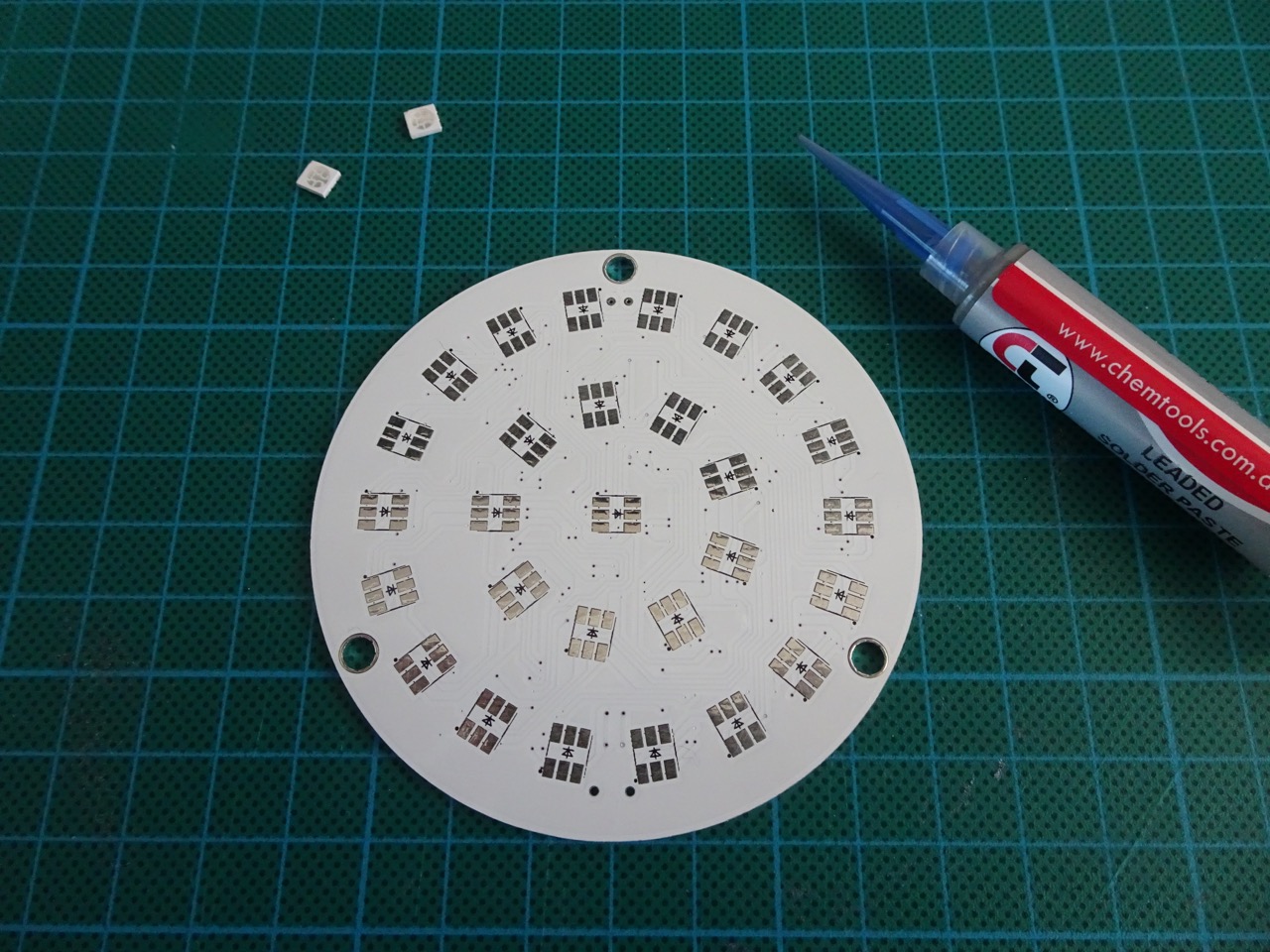
Because of the heat involved, my work mat starting to deform and I had to use a tile under the PCB. I actually thought of baking this PCB because of the number of components involved, but stuck to the heat gun in the end.
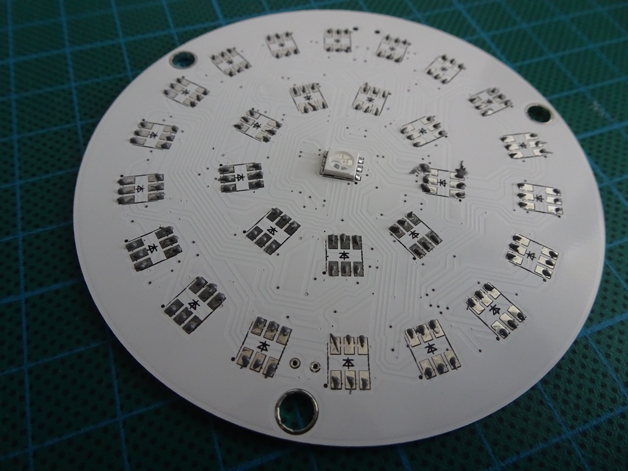
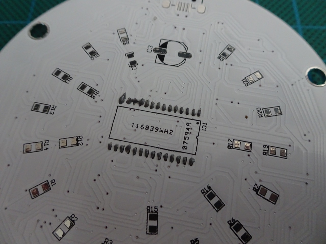
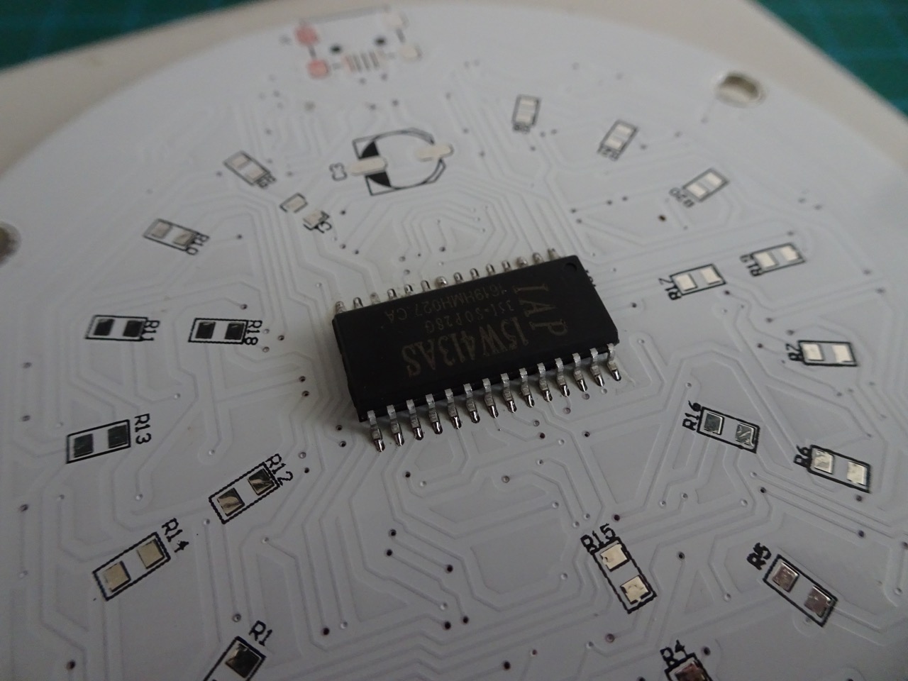
After letting the board cool down, I flipped it over and applied paste to the MCU solder pads. My soldering was perfect on one side of the MCU, but the other had two shorts initially, which I fixed with the heat gun and scalpel; that side didn't look as clean unfortunately.
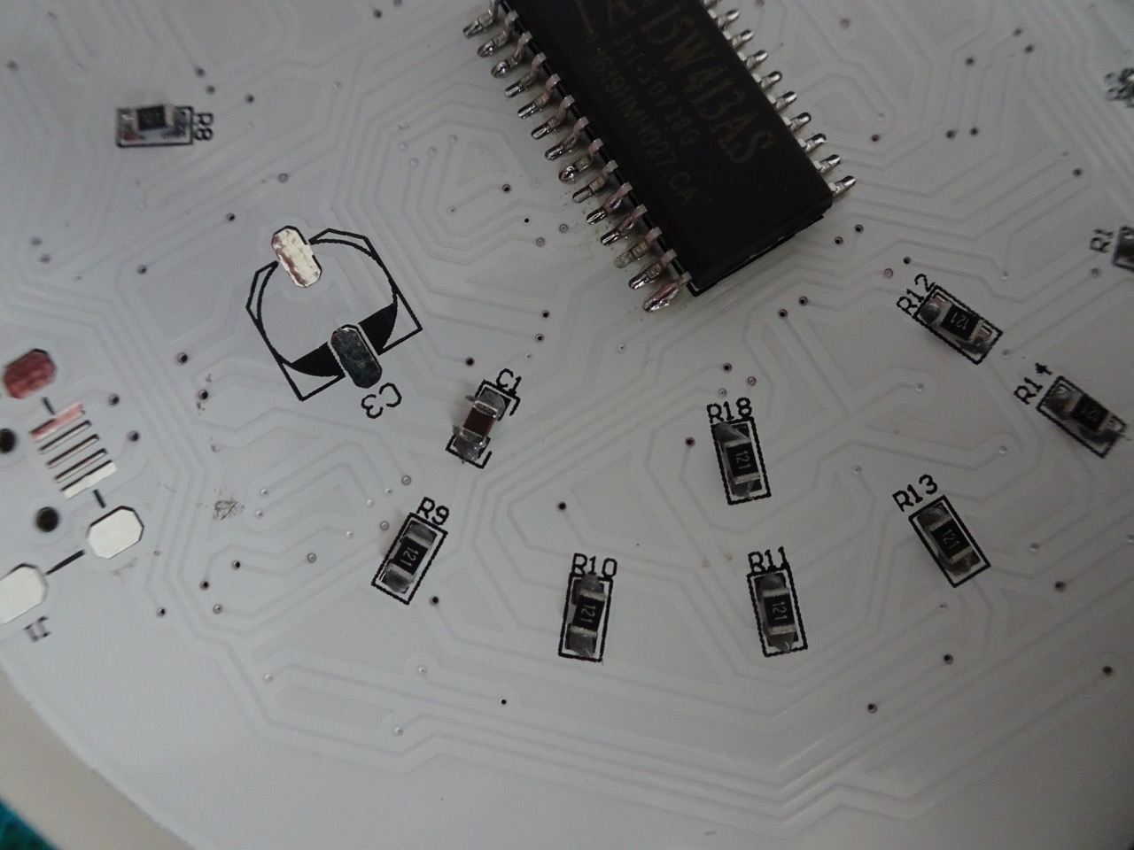
After the MCU, it was time to solder in the single SMD capacitor and all of the SMD resistors. I'd typically start with components like this and do IC components last, but because the MCU was in the centre of this board with all other components surrounding it, it made sense to do it this way.
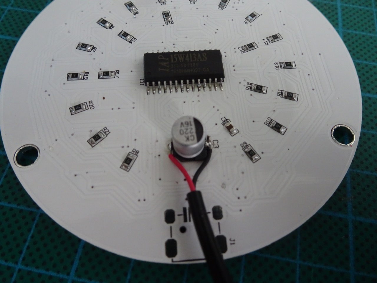
That was all for the SMD components so I switched to using a soldering iron for the remaining parts. The mercury switch and the metal-cap capacitor were soldered in by top-soldering them. I could have done the metal-cap using soldering paste and a heat gun also, but figured it would be quicker to use a standard iron. After soldering in the mercury switch, I bent it to about 45 degrees.
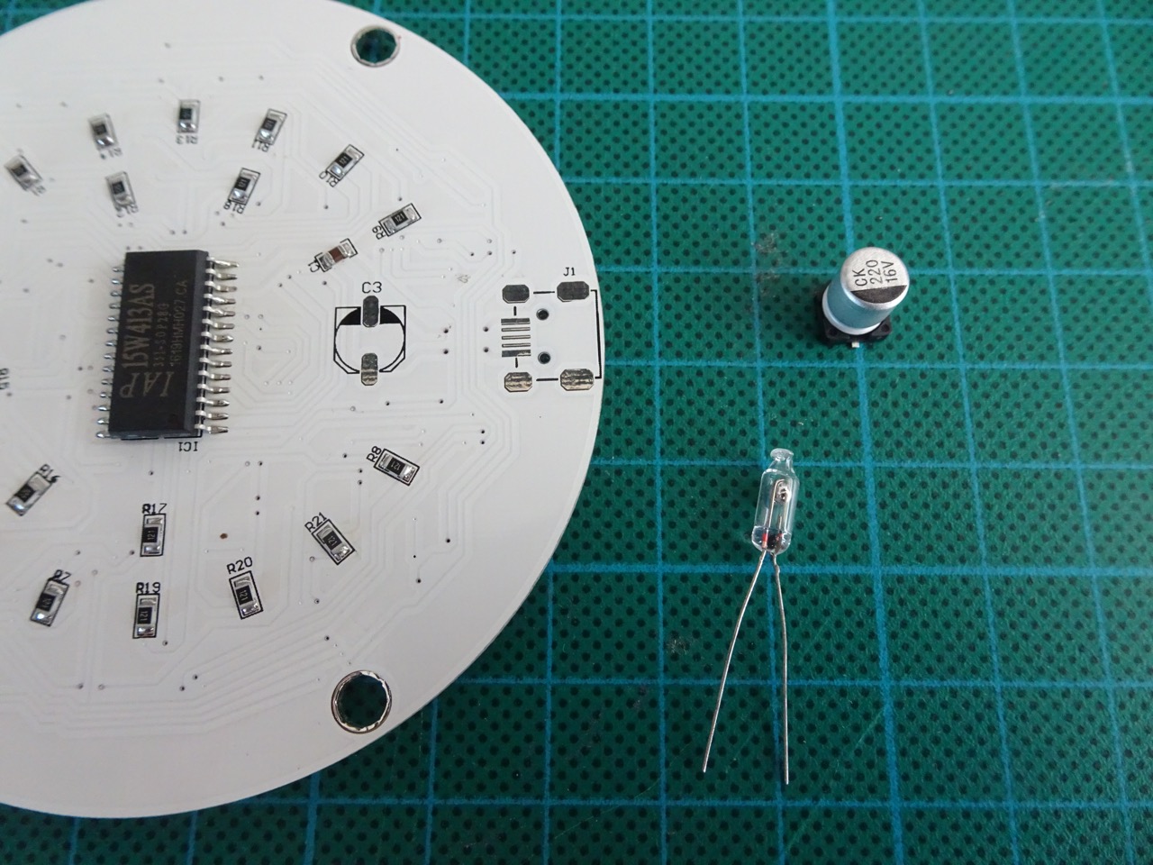
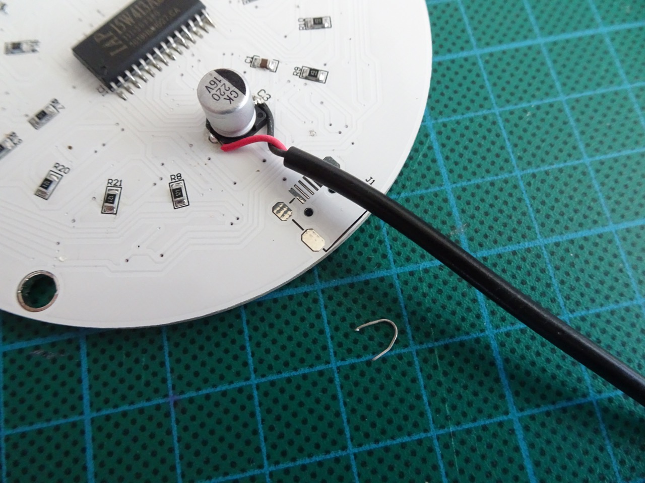
The last piece to go in was the USB cable for power. I noticed the PCB had a space for a micro-USB connector, but none was provided. The instructions showed a USB cable being soldered in directly, so I did the same. The negative (black) wire was connected to the side of the capacitor that had the black stripe, positive (red) to the other side.
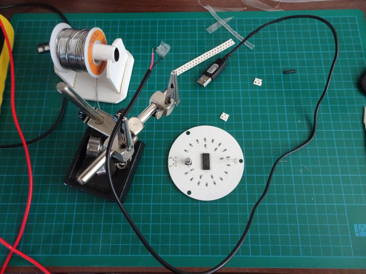
It was time for a power and pattern switch test...
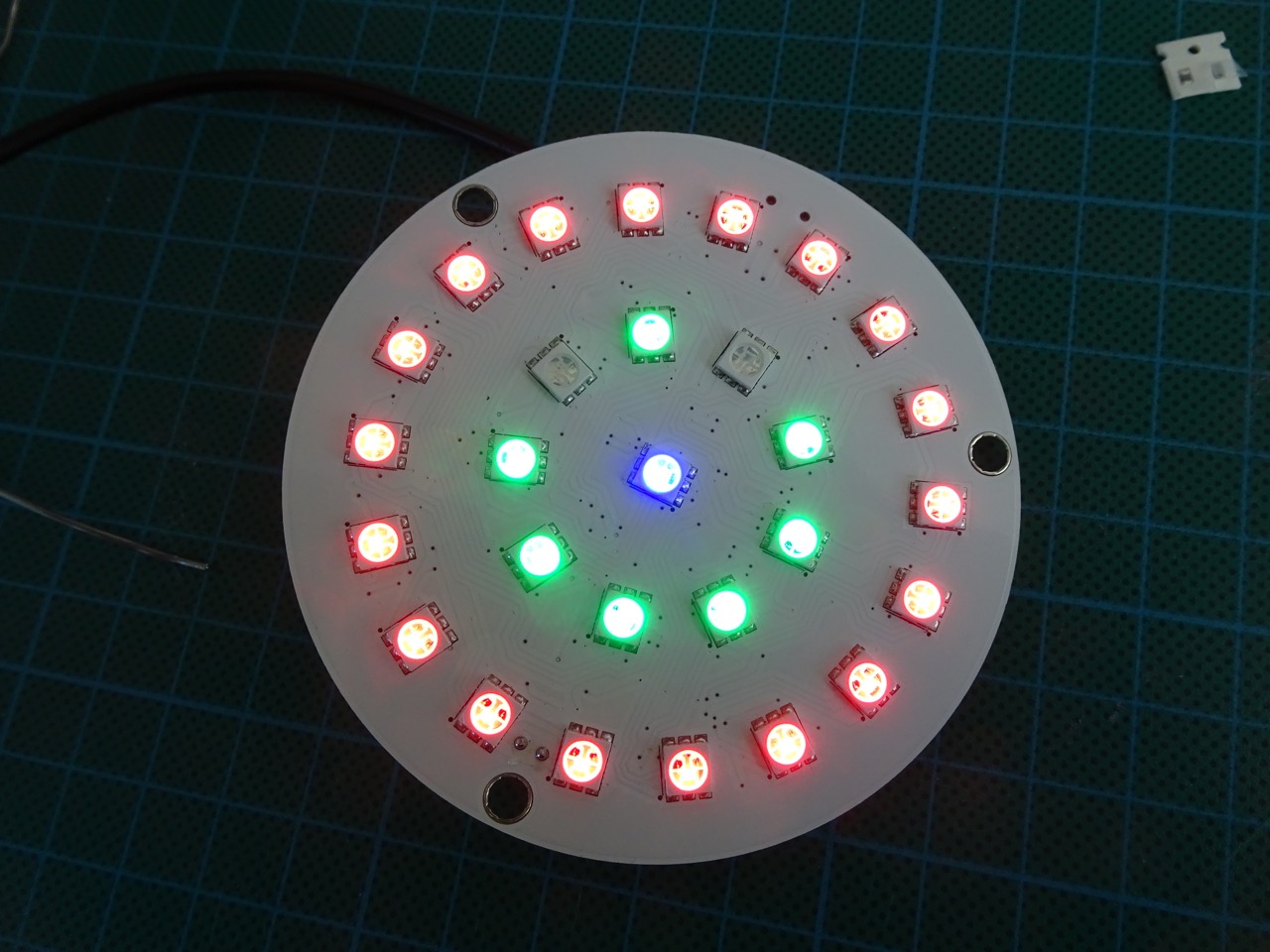
It was working!
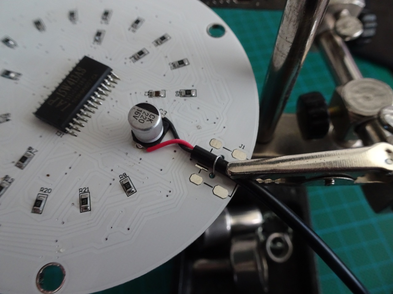
I secured the power cable to the PCB by soldering one of the cut off legs from the mercury switch over the cable.
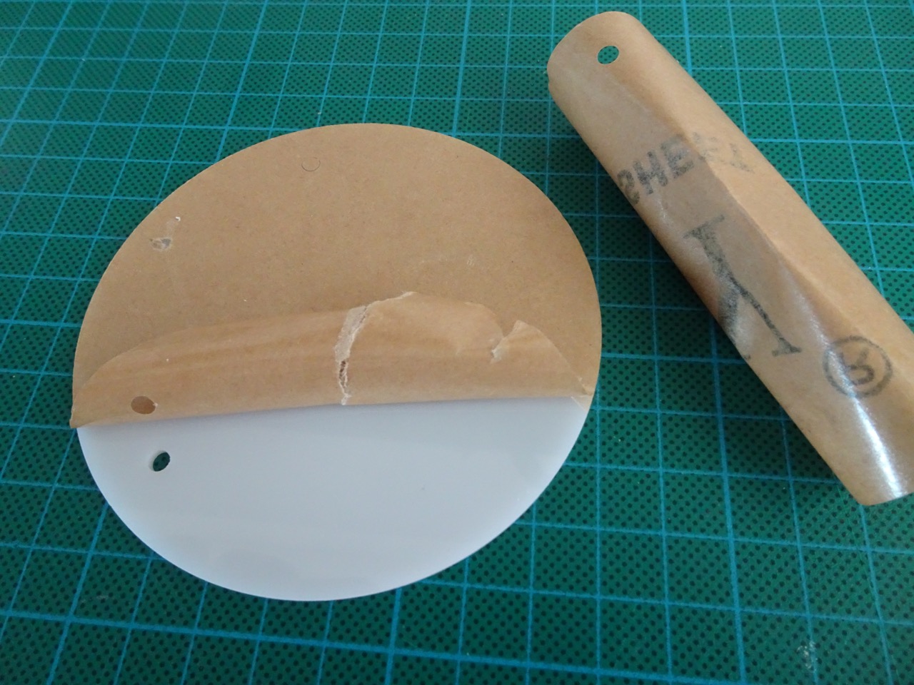
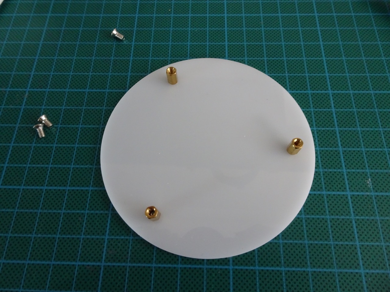
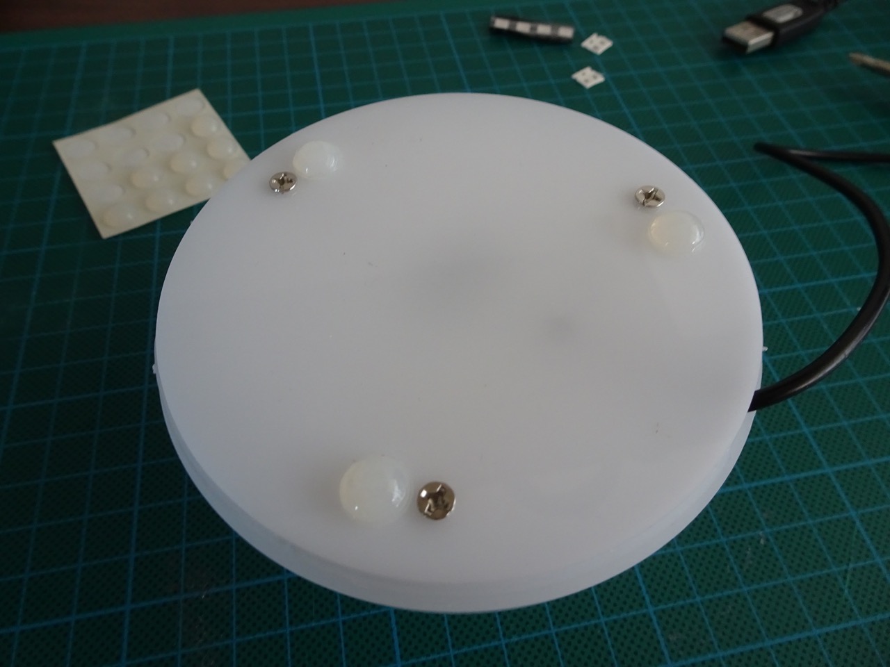
The base of the kit had to have the protective paper removed, then I screwed in the brass spacers and then secured the PCB with the LED side facing up.
I had to cut out a gap in the dome to feed the cable through and also added some rubber feet to the base because the supplied screws didn't fit flush with the bottom. This would scratch surfaces if the kit was dragged around, which I wanted to avoid. The feet were not supplied in the kit.
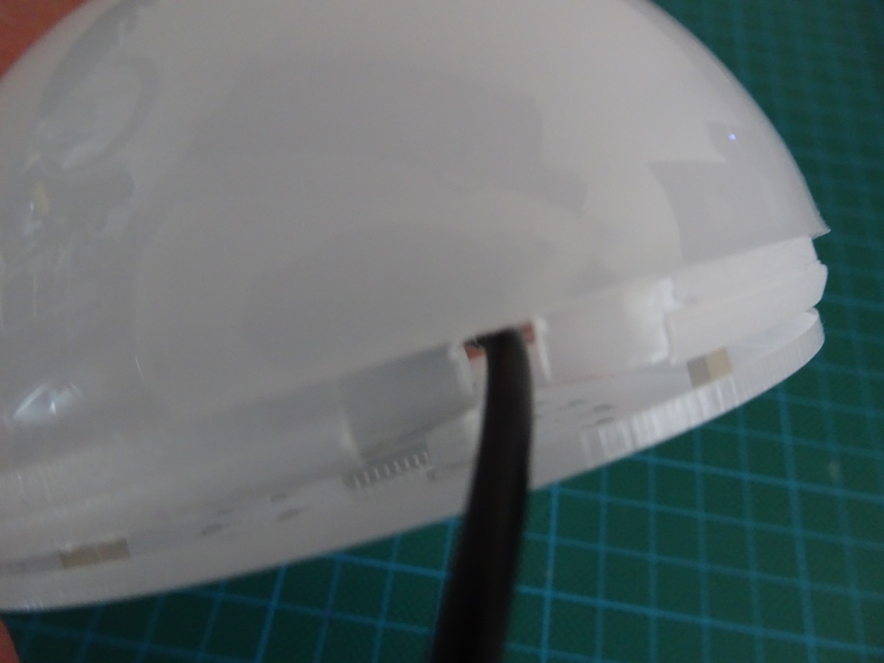
The instructions showed that the dome had to be glued to the base, I didn't do this because I didn't have any appropriate glue. However, the base and the dome sections do not fit together very well and were a real pain to align. This part of the kit was probably the biggest let down. I'll have to figure out how to secure these together better at some later point.
There was no programming involved, the kit came supplied with a pre-programmed STC15W413AS MCU. I couldn't find any details about it, but did find a similar model from STC - STC15W408AS. It appeared to be a 8051 based MCU. I wasn't too interested in programming it myself so didn't try to find out too much more detail.
The MCU controlled what the LEDs did. The mercury switch was used to switch between different modes/patterns. To switch, I had to tilt the device to trigger the mercury switch, maybe this was why they called it a gravity sensor. I quite liked all the different patterns that were produced though I wish there was a setting that rotated through all of them without having to switch manually.
Overall this kit was an interesting build. It certainly fulfilled its intention as an SMD soldering practice kit for me. I liked that there were components on both sides of the board and that the board was white - not something I see often. PCB quality was great, but housing quality was terrible I thought. There are other similar kits from Geekcreit that I'd like to get in the future, if I do, I'll be posting their assembly details here too.
-i
