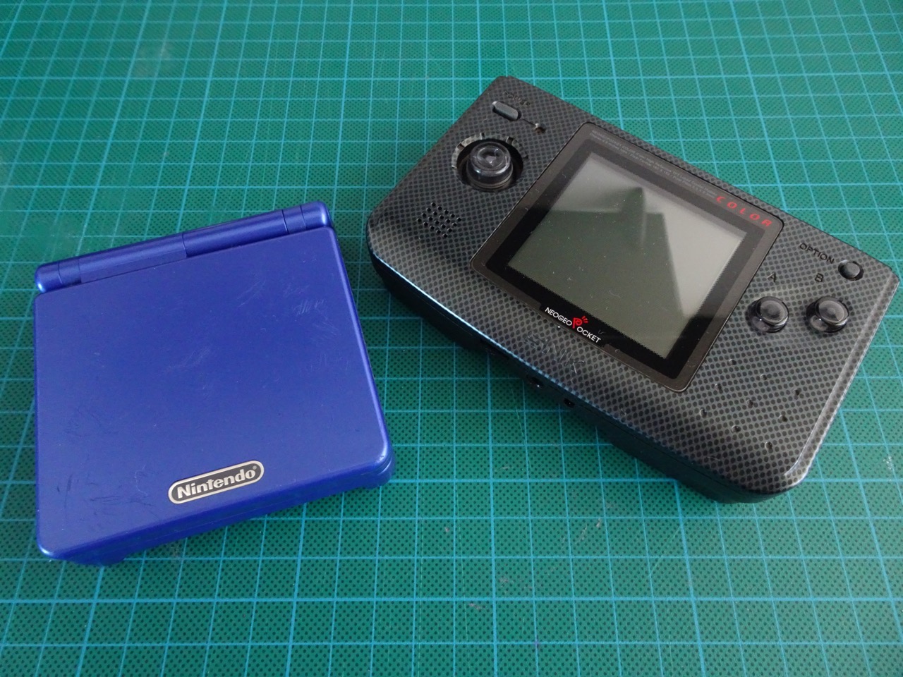
This guide shows how to take out the Game Boy SP Model AGS-001 Front Light and put it into the Neo Geo Pocket Color. If you do this mod, make sure you get the correct Game Boy model. I would also recommend getting a broken one (like I did) so that you're not ripping apart a working console. This mod is not intended for the B&W version of the NGP as that has a different screen that can be back-lit.
Tools and parts you will need
- Phillips Screwdriver
- Flat head Screwdriver
- Tri-wing Screwdriver
- Scalpel/Exacto Knife
- Needle nose pliers
- Soldering Iron and solder
- Wire Cutters
- Game Boy SP Model AGS-001 Front Light
- 3mm LED (optional)
- 47 Ohm 1/4W (1/2W is fine too) resistor
- 10" of 30 awg modding/Kynar wire
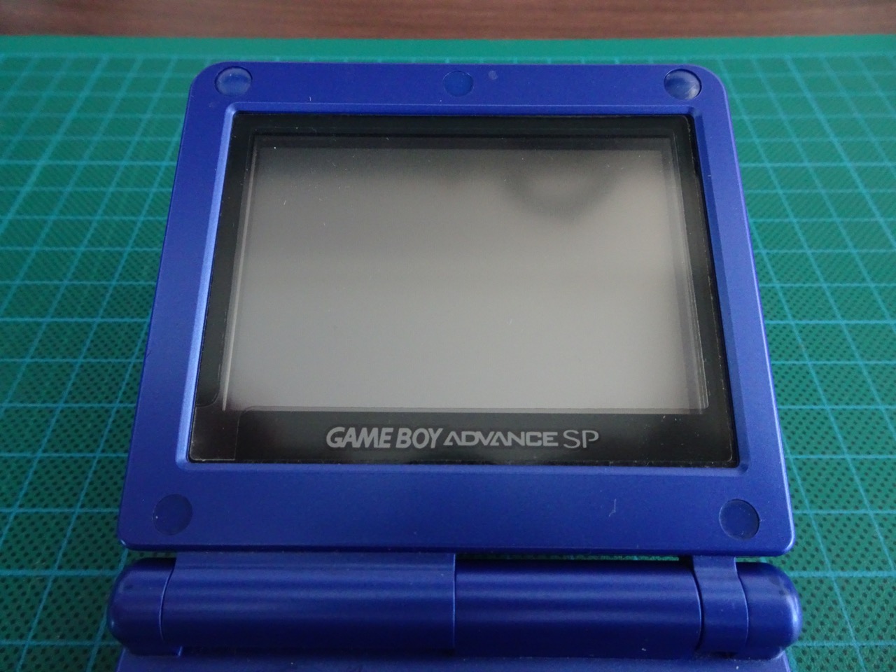
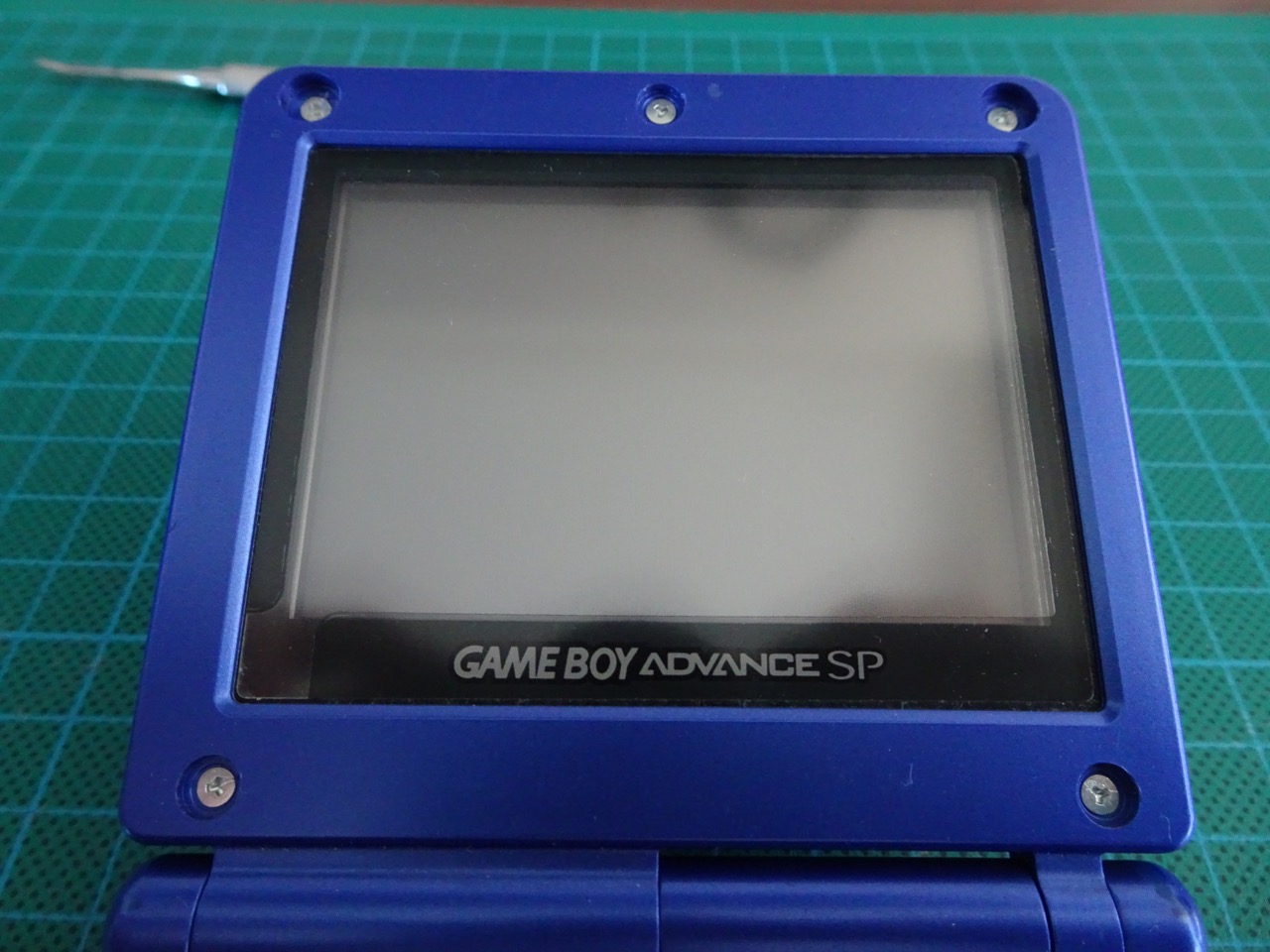
Opening the Game Boy SP
This step requires a tri-wing screwdriver. There are 5 rubber plugs covering the screws on the front of the SP screen enclosure. The plugs are made out of rubber and can be pried out with a scalpel or screwdriver.
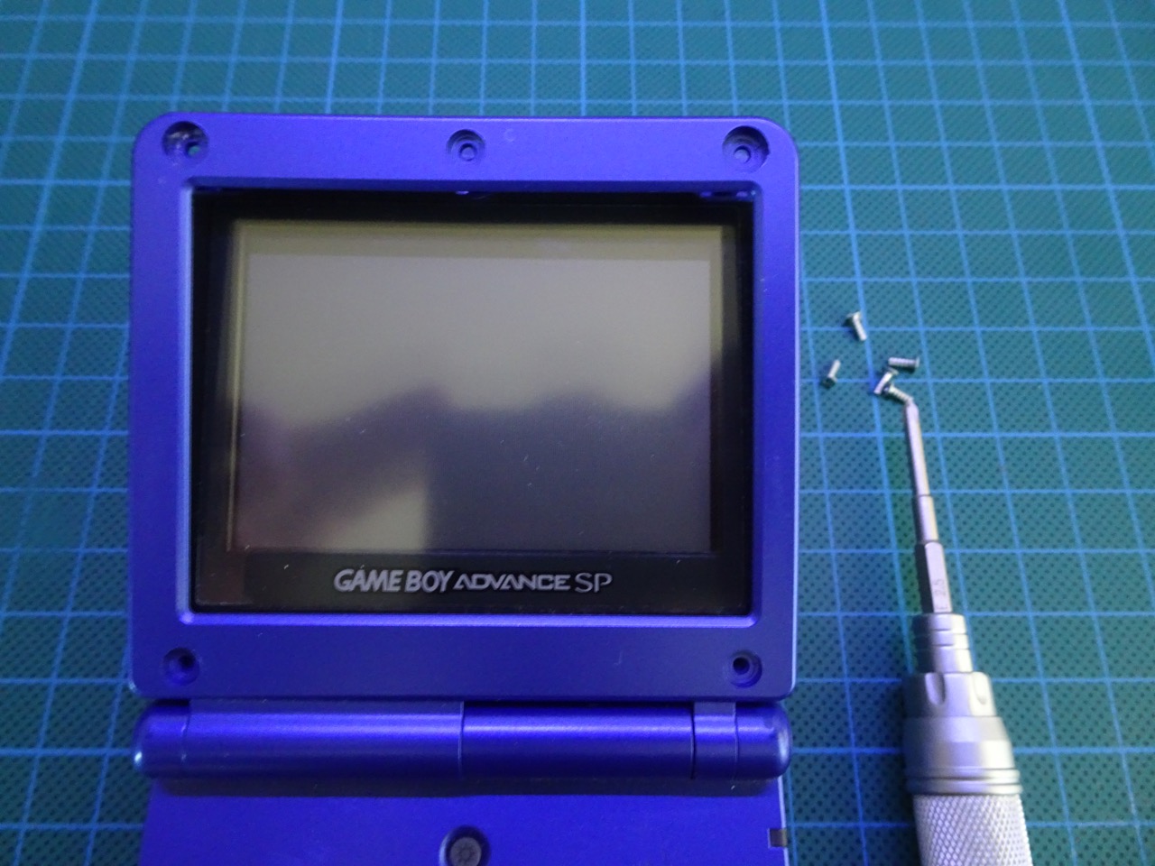
Once the screws are all out the screen should come apart into two sections quite easily. The back can be removed and put aside now as it will not be needed.

Desoldering the front light
This step may seem tricky at first but it really isn't. With a soldering iron heat up the two pads and use a scalpel to pull up the ribbon cable from the bottom. Be careful not to rip it. The ribbon will come up once the solder joints are free.
Removing the front light
Next the LCD needs to be removed from the front light housing. This can be done by using a flat screwdriver to pop out the LCD. There are small tabs (2 per side) holding it in. Once the LCD is out the front light assembly is the piece we are after. From this point be very careful with the front light, it is made out of glass and is very fragile. Be sure not to touch it except on the edges as it will be extremely difficult to clean from any oils you have left on it from your fingers.
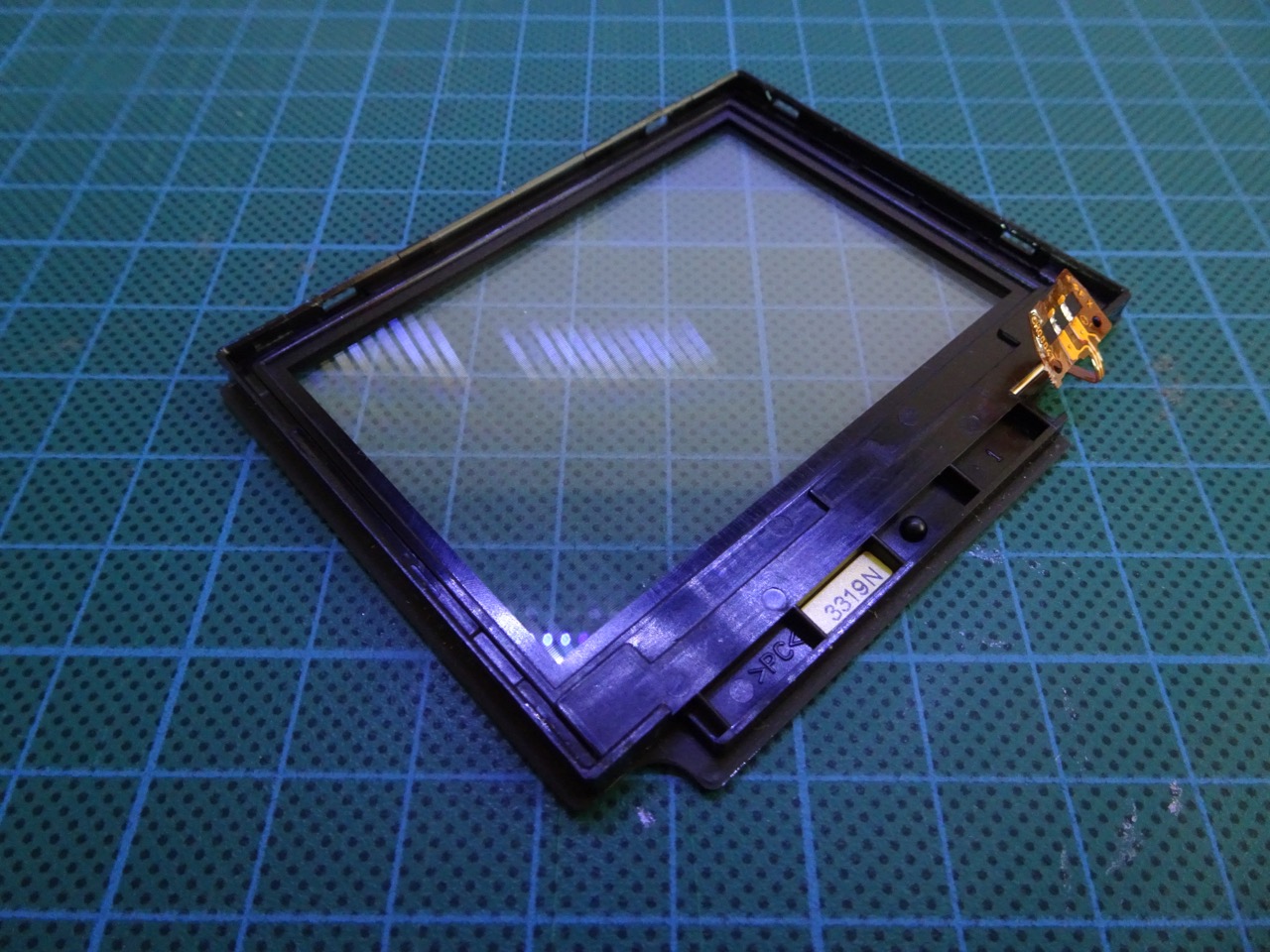
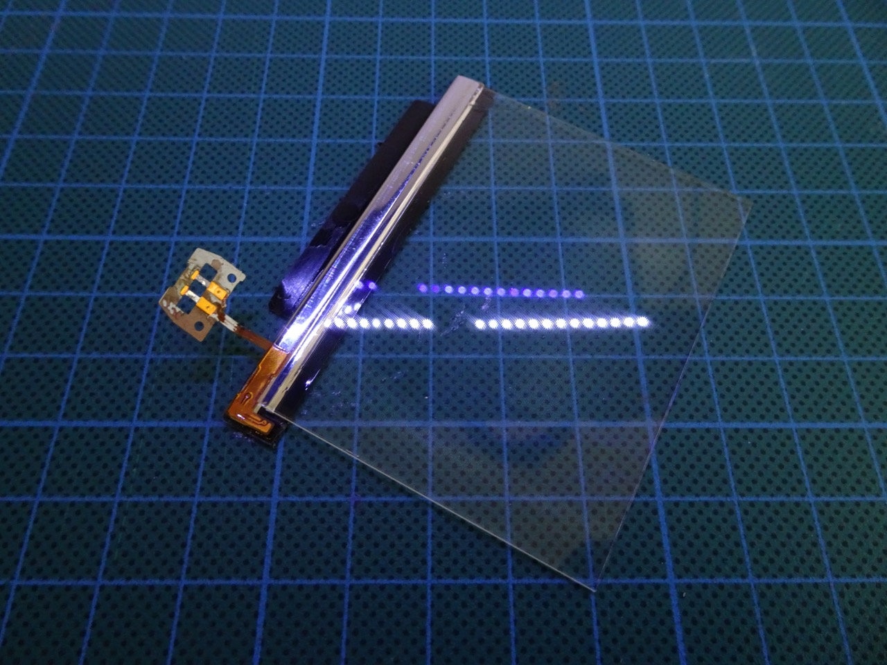
The front light assembly has a plastic protective cover on the front face of the enclosure. This needs to be removed. Using a scalpel and cutting through the glue between the plastic and the front cover the result should be something like this...
That black tape is very sticky and needs to be removed. At first I didn't remove all of it and opted to keep the bottom part intact, however later on I ended up removing all of this tape so I would recommend removing it all straight away. The metal part is the LED housing for the front light and the glass is a polarised thin wafer. If the glass pops out of the metal housing it is easy to push back in but be careful not to crack it and put it in its original orientation.
Opening the Neo Geo Pocket Color
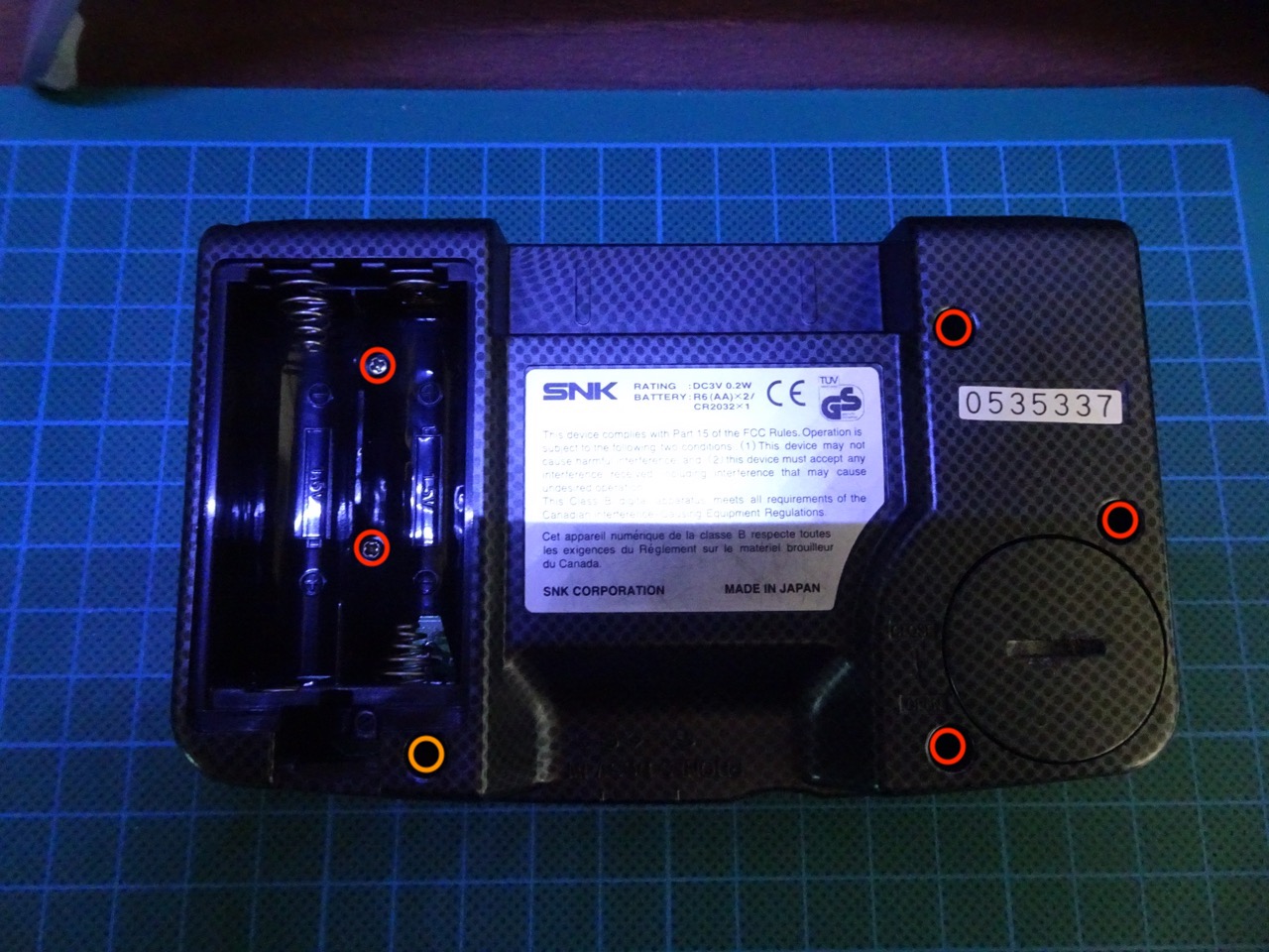
There are 5 Phillips type (red circle) screws and 1 tri-wing (orange circle) screw holding the NGPC together. Then there are a further 3 Phillips screws inside holding the board down.
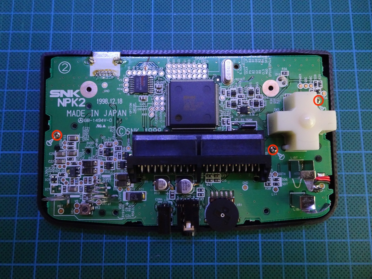
The speaker wires then need to be desoldered.
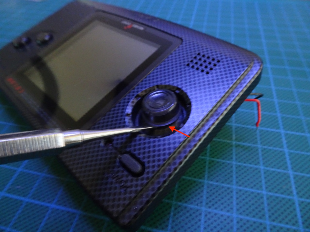
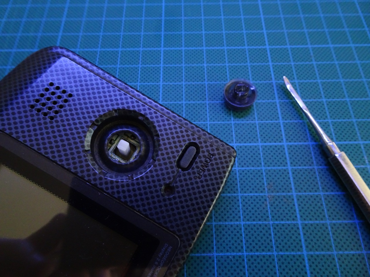
Next the joystick can be removed. This is not hard to do, the joystick should be pushed up with something flat and it will slide out with a little bit of force.
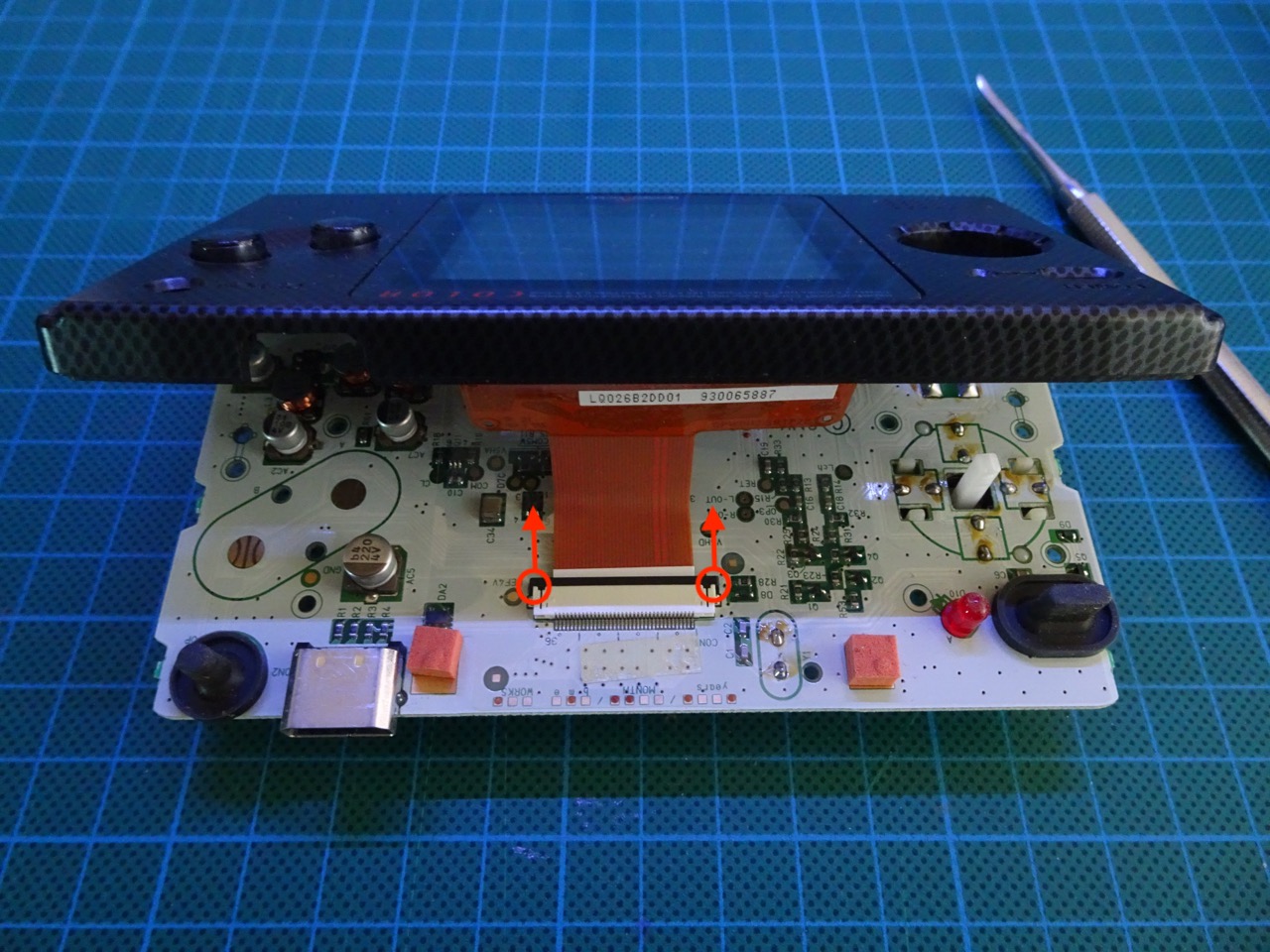
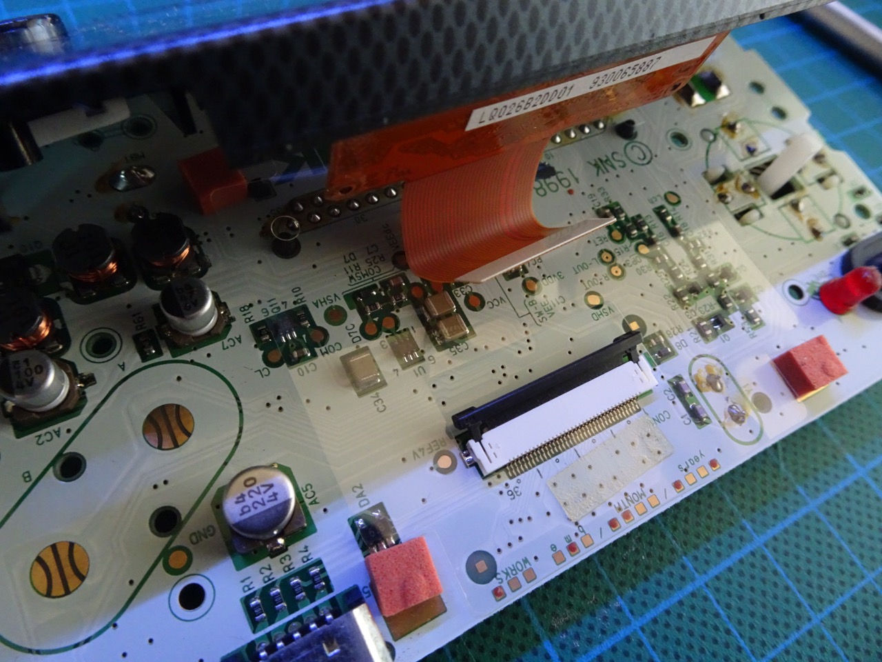
Disconnecting the screen
The screen is connected by a single ribbon cable. There is a ZIF socket that holds it in place. To disconnect the cable first the tabs on either side of the socket need to be slid up (see photo for orientation). Once the tabs are free the ribbon should come out quite easily.
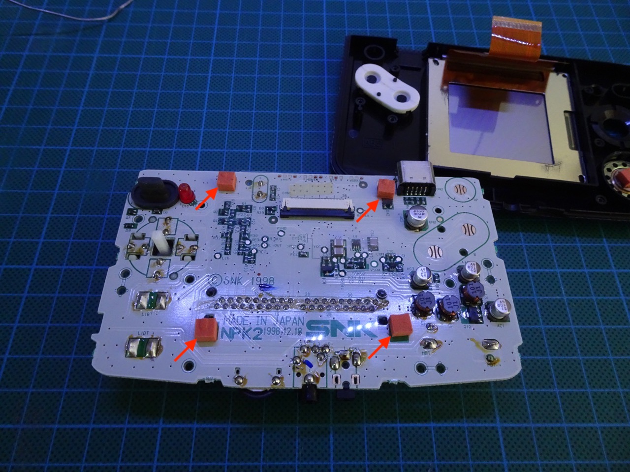
Making room inside the case
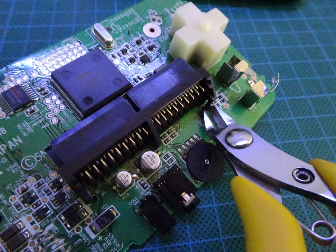
To make the Game Boy front light fit, extra room needs to be made inside the NGPC. The orange foam pads need to be removed, these have adhesive holding them in place and can be removed easily. Then the four tabs that are 'holding' the cartridge slot in place need to be sheared off. They are not necessary to hold the cart because it's being held in by all of the soldered in pins.
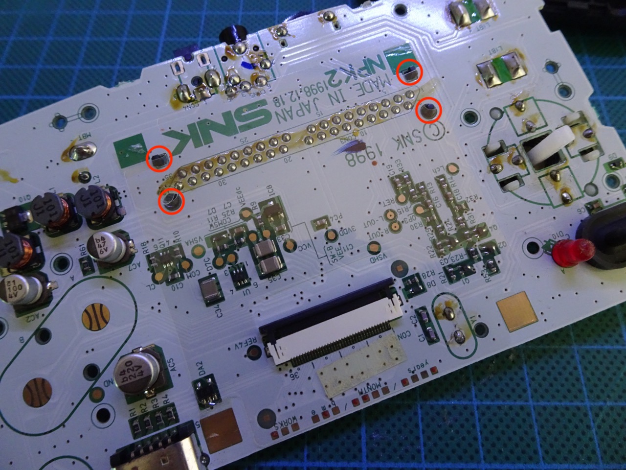
Two of the tabs are easier to cut off from the back side of the board.
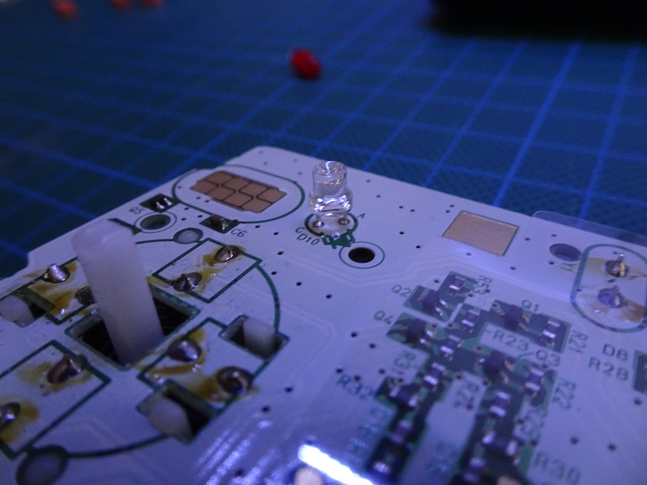
Replacing the LED
This is an optional step and in hindsight I do not recommend it (a bright LED is too distracting when playing games). However if you want to change the LED from the standard red to a bright blue or any other colour all you need is a 3mm LED. Simply desolder the old LED and solder in the new one.
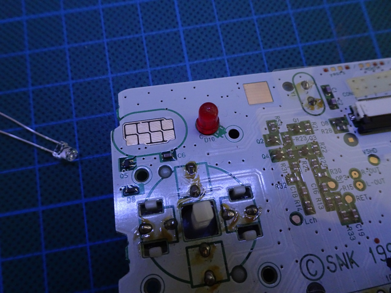
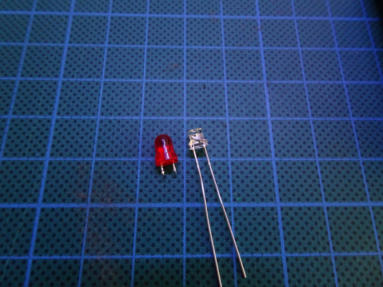
When soldering in the new LED make sure its top is at the same height as what the original was. The easiest way to do this is to put the old LED next to the new one and simply align them. The LED's + and - pins need to be placed in their correct holes in the PCB. The easiest way to do this is to look for the "flat" side on the original LED - it's pointing towards the top of the board, then make sure that the new LED's "flat" side is facing the same direction.
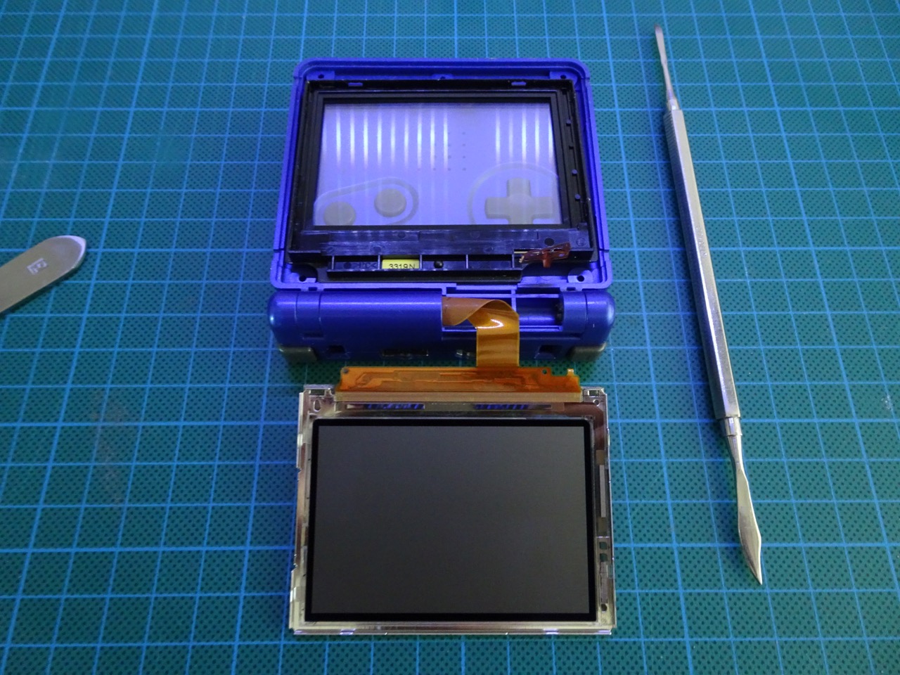
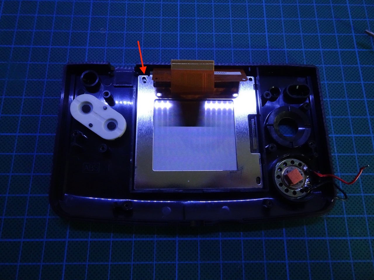
Removing the NGPC LCD
The LCD needs to be popped out of its housing. Using a flat screwdriver from the top left side is the easiest way. Do this gently and once the top left corner has lifted off, go around the rest of the edges and separate the LCD from the case. There's adhesive holding it in place in some places. Be very gentle here so not to crack the LCD.

Installing the front light
Unlike in the original guide, I removed all of the internal plastic that held the original LCD in place. I did this because without doing that I couldn't get the front light in the correct place and it was covering a portion of the LCD when installed.
Removing the 3 tabs is simple. Using a scalpel cut the corners between each of the tabs first. Then score the bottom of each and finally use the needle nose pliers to bend them down and then up again. They should snap off at their bases and come out.
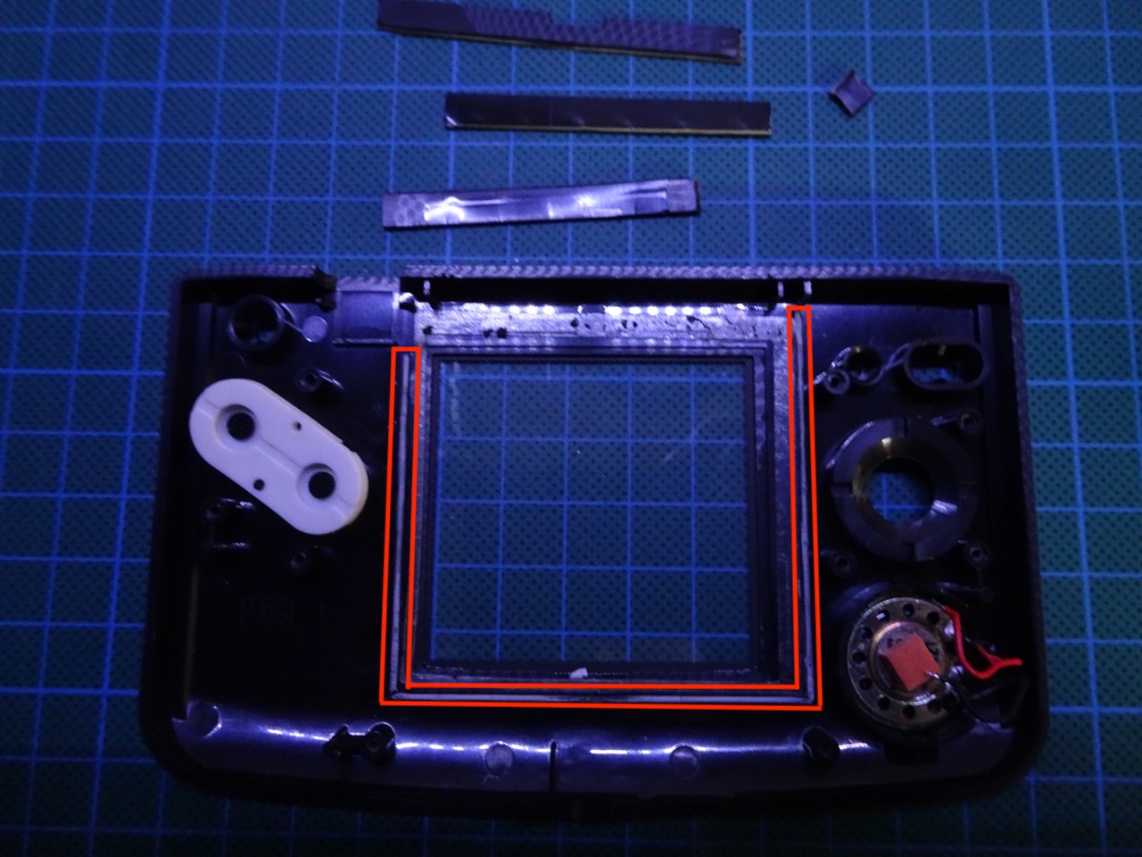
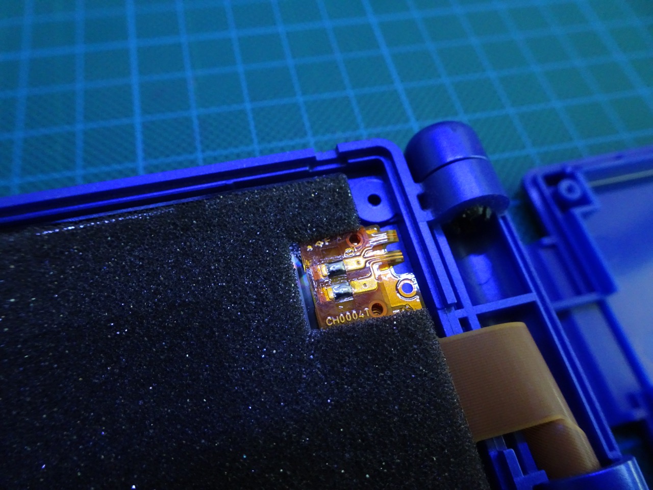
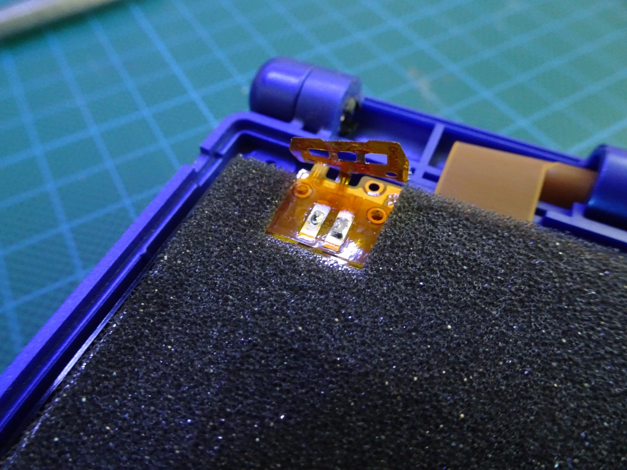
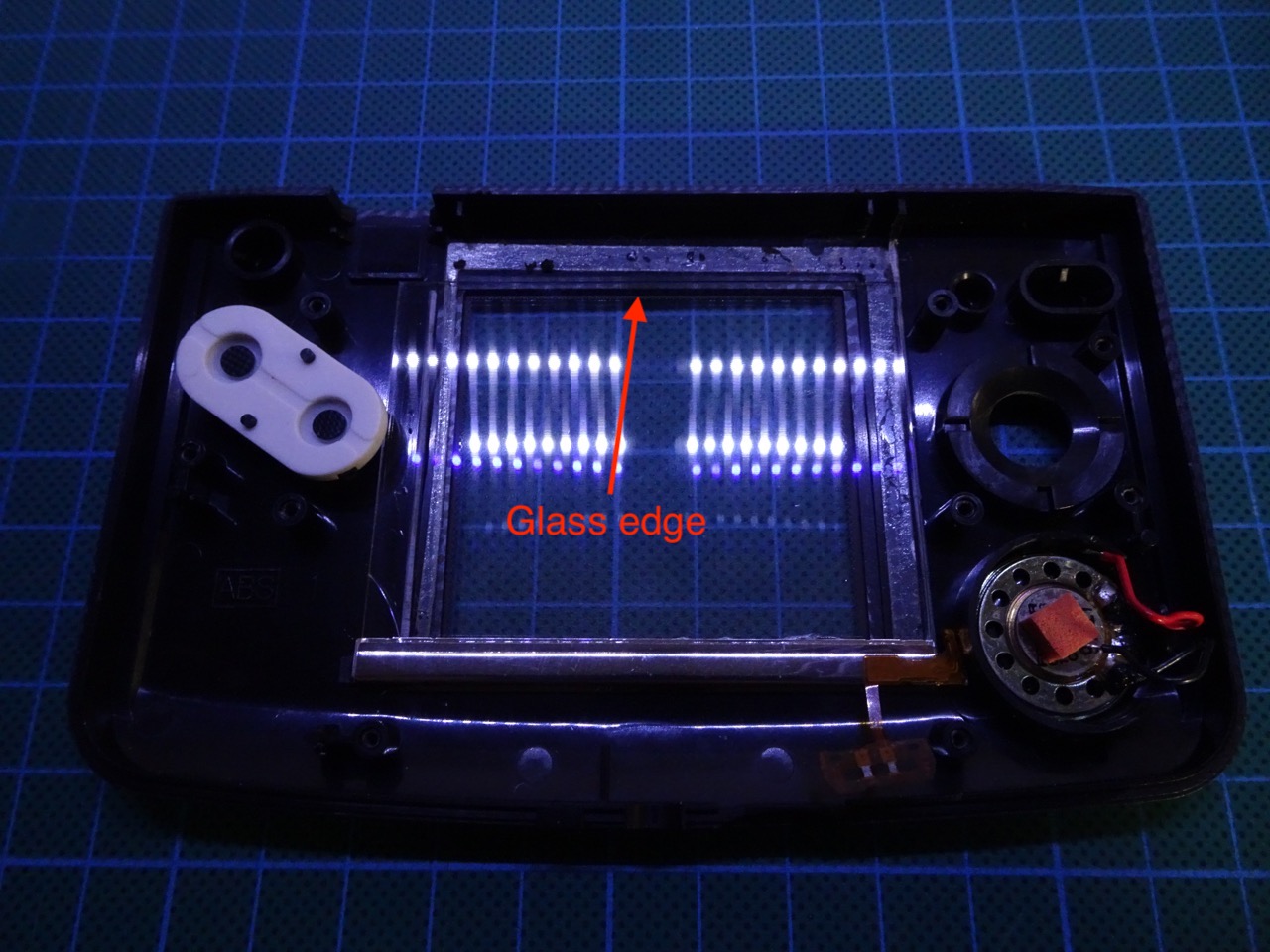
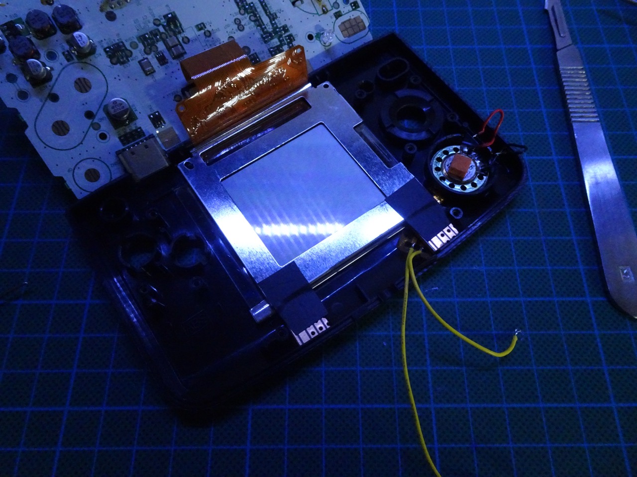
Before installing the front light make sure there is no dust or fingerprints on the inside of the NGPC glass. Then take the front light and align its top edge of the glass with the NGCP front glass where the black dots are printed. The metal part of the front light should be towards the bottom edge and should not protrude past the black dots on the bottom. If it protrudes then the NGPC LCD will have its bottom lines covered. Make sure the front light ribbon cable is on the right hand side.
Re-installing the NGPC LCD
Since all of the original tabs that held the LCD in place are gone, it has to be aligned manually. This isn't hard to do just look straight down and align it to where the old tabs were - it's visible through the front light glass. Use some electrical tape to hold the LCD in place.
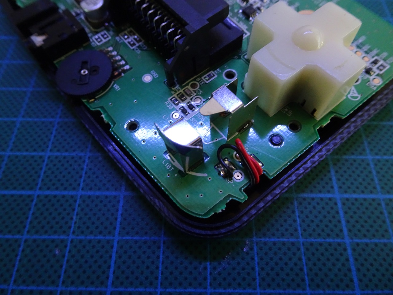
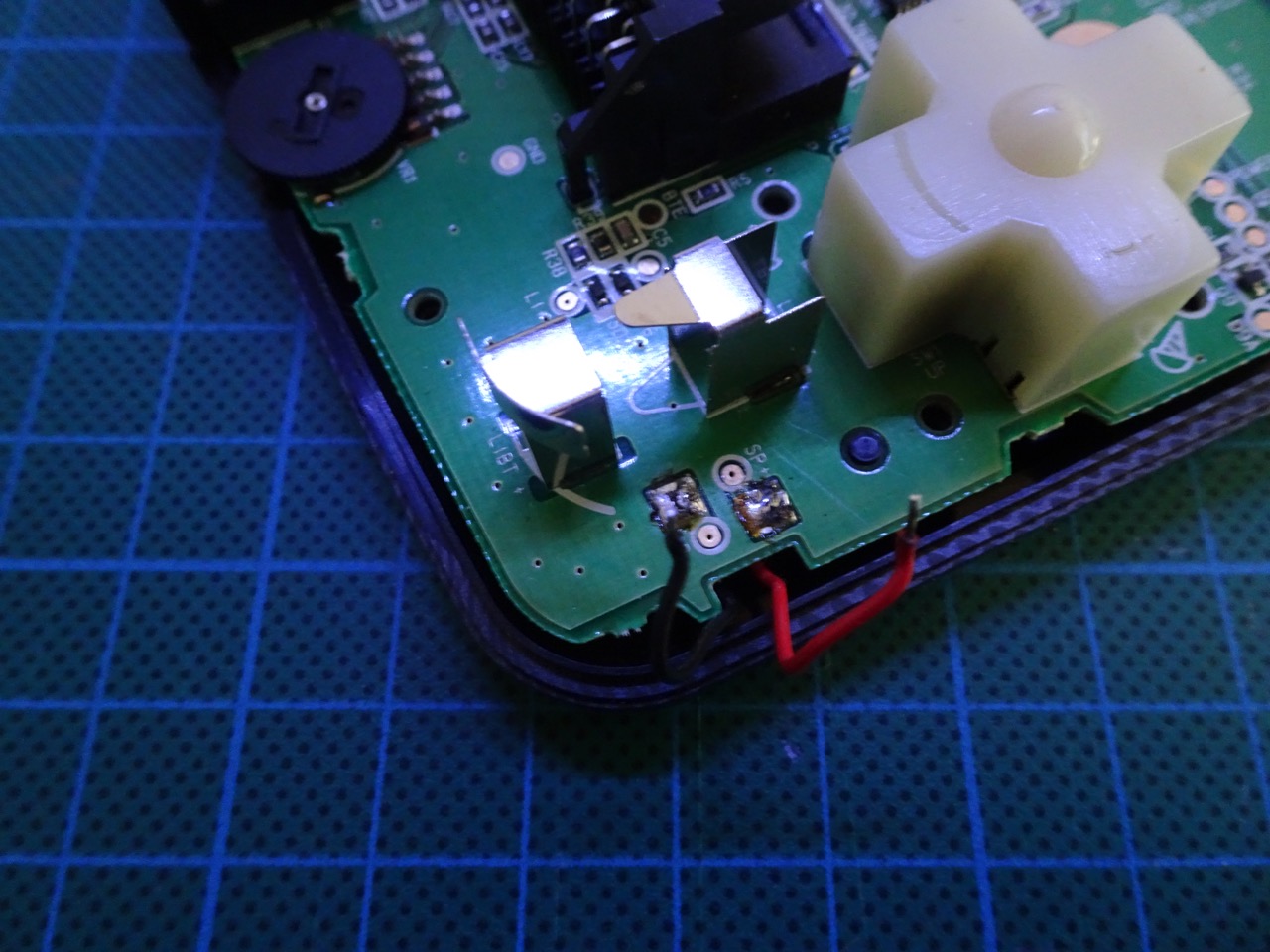
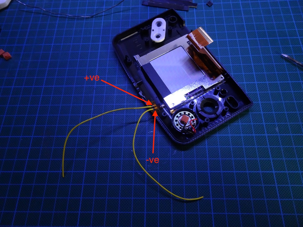
Solder two wires to the front light. The rightmost pad is the negative/ground an the leftmost is positive.
The LCD can be held in place just with electrical tape but I wanted it to be a bit more secure so I cut off some lengths of PCB breadboard I had laying around and wedged them between the case and the LCD. This worked pretty well and so far has survived a plane trip and a few days on the road so it's sturdy enough.
Wiring in the front light
Now the LCD ribbon cable can be reconnected. The tabs on the ZIF socket have to be slid back down after the ribbon is in place. The main board can be put back and attached with its three screws. Make sure that the buttons are back in their correct positions first, if they happened to have fallen out. Be careful to pull the wires out prior to screwing the board down.
The negative wire from the front light can be attached to any GND point, I used the one on the right below the cartridge slot. The positive wire must first be connected to the 47 Ohm resistor, and then to the left side of the C20 capacitor. Speaker wires can now be re-soldered too.

Finishing up
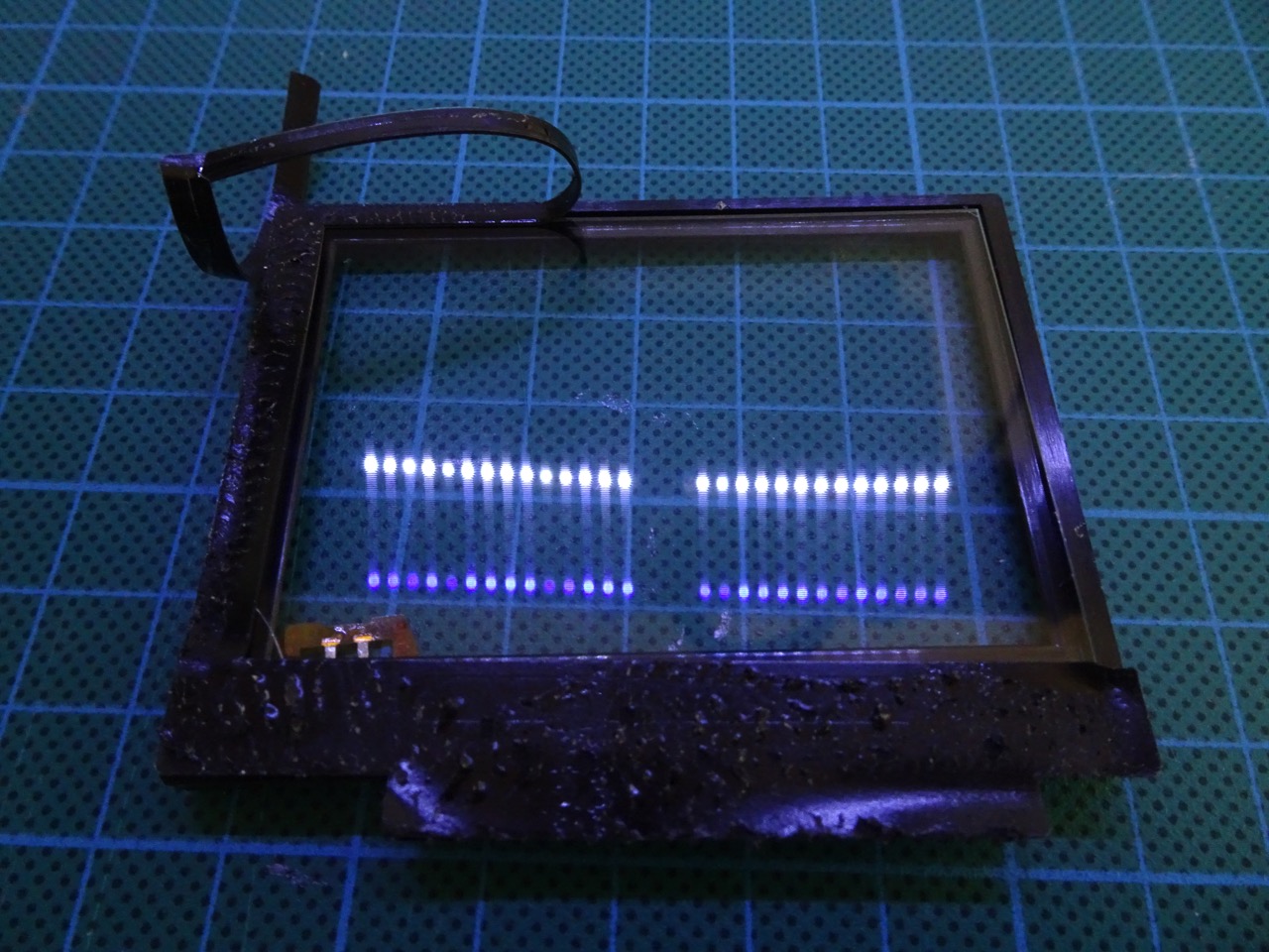
The rest of the case can be re-assembled now. Don't over-tightent the screws. The result should be a screen that lights up and can be seen in the dark.
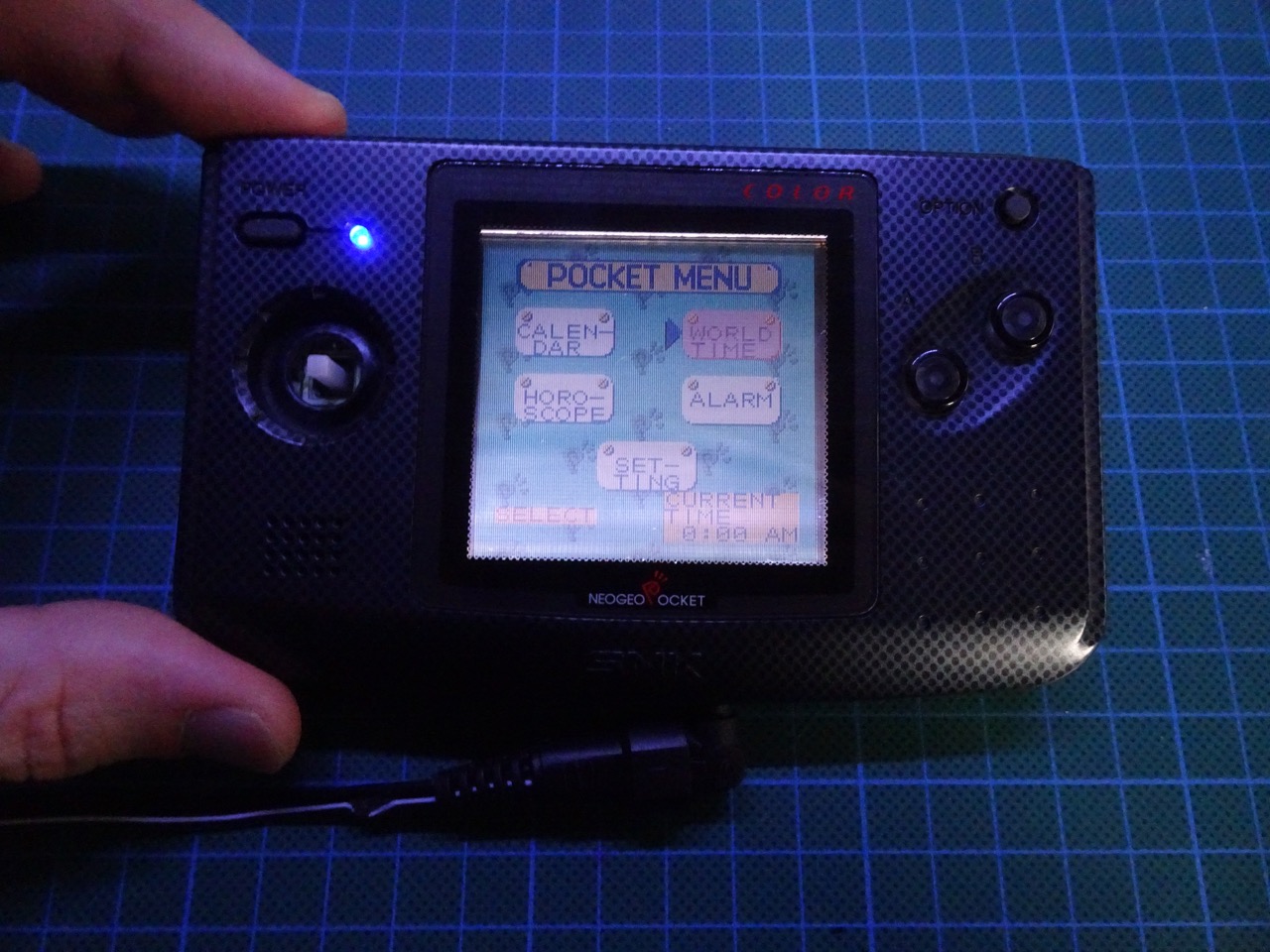
When I first did this mod and turned the NGPC back on I had a screen that was completely white. This happened because I somehow got the front light in reverse (it came out of its housing for me and I must have replaced it the wrong way around). This was easy to fix but required me to disassemble the NGPC, take the front light out and flip the glass around.
I've also experimented with different values for the resistor, 47 Ohm gives the best results, others are just way too dim. I would like to add a micro switch in the future to be able to turn the front light on and off though.
I'm still not quite happy with the results because the screen is lit up unevenly. This is mainly due to the bottom of the front light being thicker than the top (because of the LED housing). This ends up producing that strange banding visible in the photo on the bottom of the screen. I plan to use some thin metal to even out the top and bottom parts of the front light in the future. Will post an update once I do that.
I'd also like to try and see if I can use LOCA to secure the front light to the LCD. It's not something I've ever tried in the past but from what I read the results it produces are quite good.
-i
