Overall the kit is quite good. The end result is a nice looking unit. My biggest complaint is that microphone input doesn't work very well unless you put it very close to the speakers. Line In works very well, however I couldn't find many ways of connecting it together with speakers (I have USB speakers) or an A/V receiver at the same time.
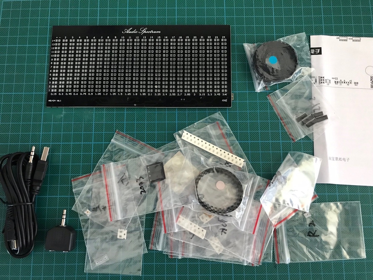
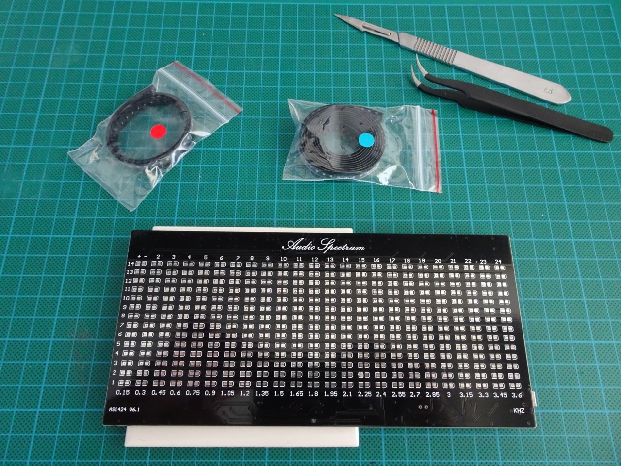
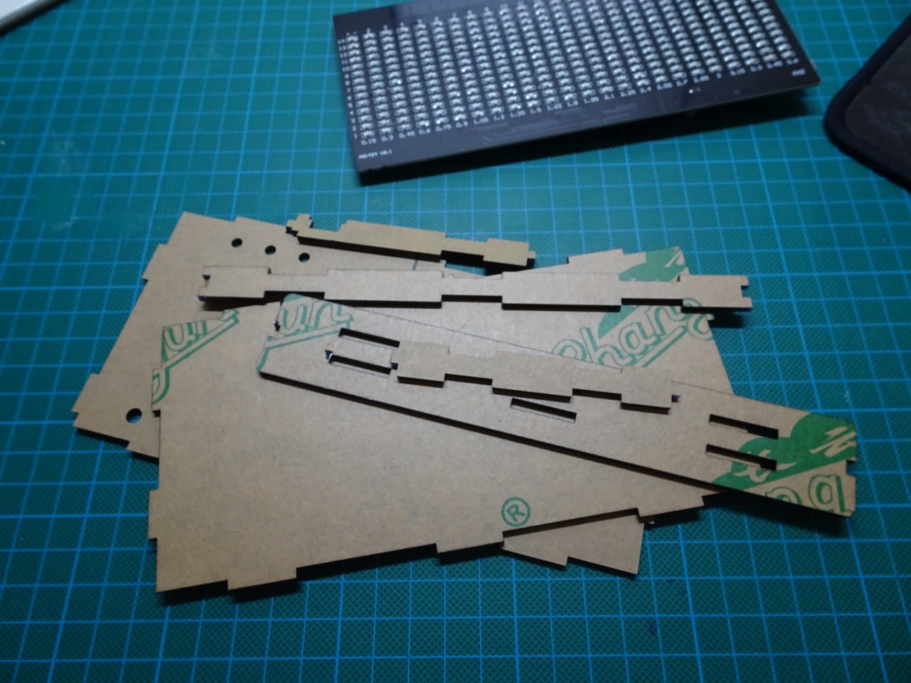
This isn't a review of the kit, it's more of a guide on assembly because...surprise, surprise...you will not get any English instructions with this kit! The kit includes an acrylic enclosure, all of the components, cables, audio splitter adapter and a sheet of paper with the parts list and what appears to be a user manual. The parts list is easy enough to follow - all of the included components are clearly marked in their own zip-lock bags and correspond to the list. There are a few items on the list that are pre-soldered in - U1, U2 and the R15 resistor array. Also the P1 and P2 headers do not have anything to fit in them and can be ignored.
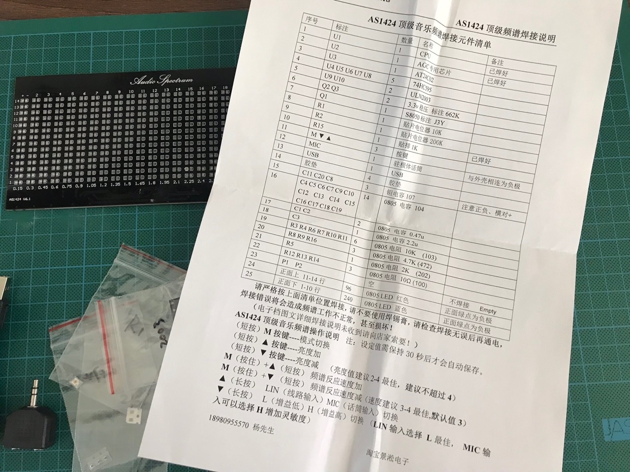
The instructions were a little bit more difficult to follow but I did manage to find an English translation...
Button control:
Short press: M - mode switch.
▲ - increase brightness.
▼ - reduce brightness.
(Recommended brightness value 2-4).
M (hold) + ▲ (short press) - increase spectrum speed.
M (hold) + ▼ (short press) - decrease spectrum speed.
(Recommended speed 3-4).
▲ (long push) - switch between LIN (line input) and MIC (microphone input).
▼ (long press) - switch between L (low gain) and H (high gain) (L is the standard, you can choose H for MIC and car music spectrum).
Note: you must hold the setting values for 30 seconds before they can be saved automatically.
Potentiometer function:
Input adjustment potentiometer: for adjusting the input signal, for example, if the input signal is too strong, it can be lowered, or set this potentiometer to remove background noise to protect some devices.
Spectrum display amplitude potentiometer: for the maximum amplitude display by AGC (automatic gain) method is set. After the adjustment, automatic gain will take this setting value to automatically adjust the maximum amplitude. (You can disable AGC function if you do not need it).
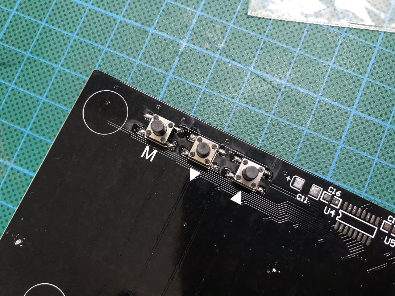
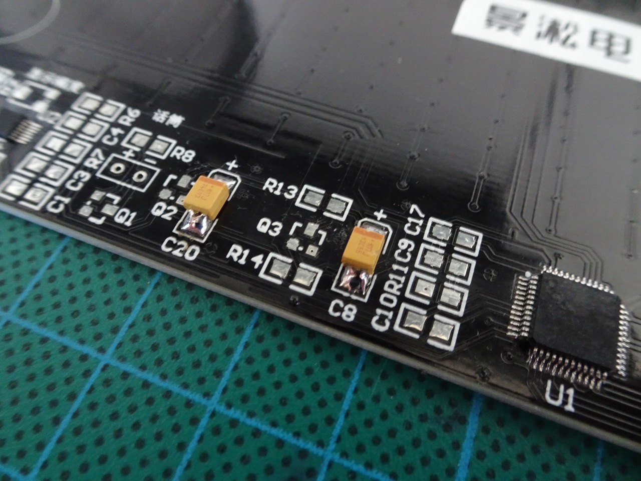
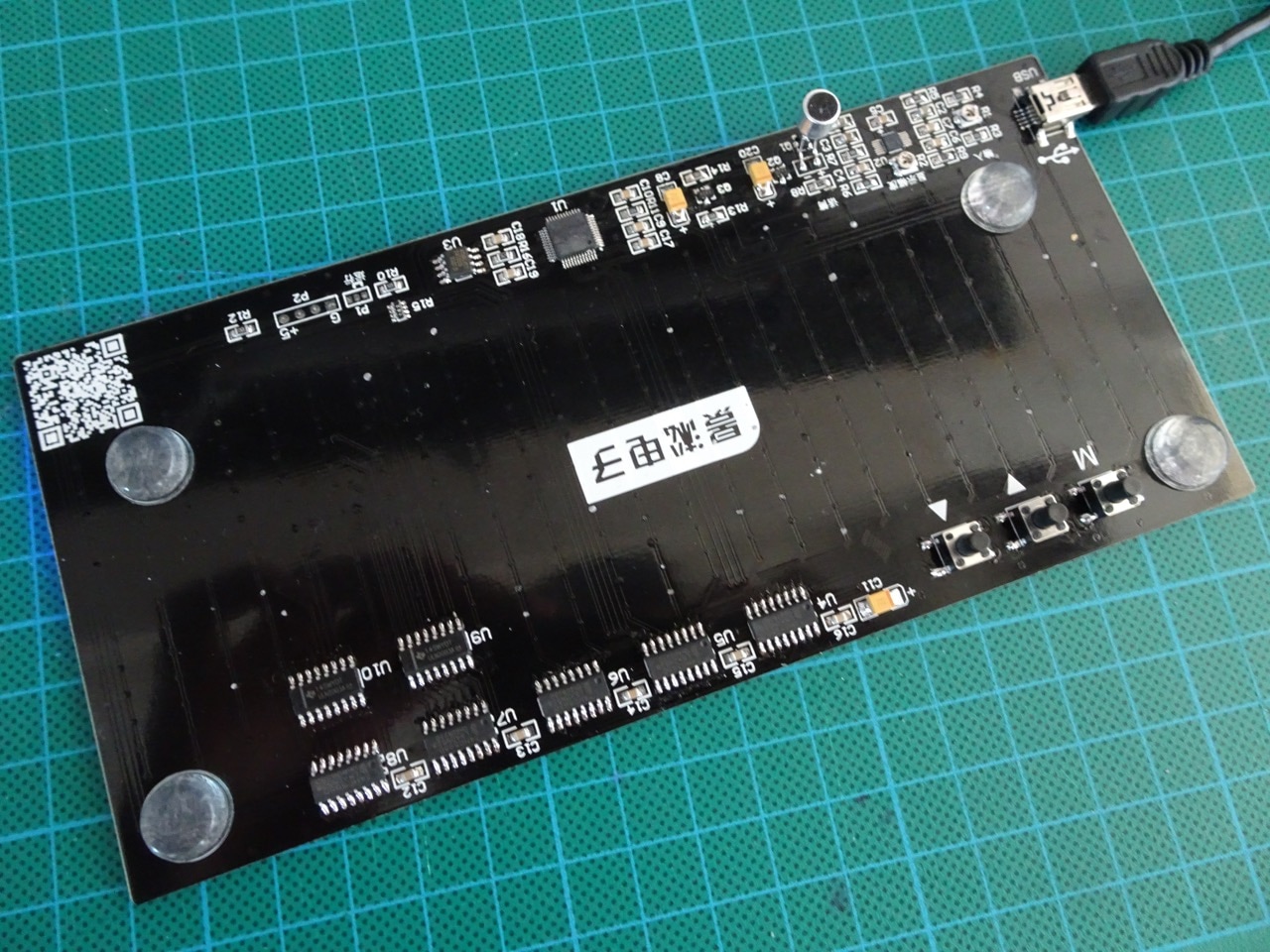
Ok lets get to the assembly. I started with the bigger components that I could solder in using a regular soldering iron. There weren't many of those, just the switches and the tantalum capacitors (C8, C11 and C20). The +ve side of these caps was marked with a band, which was a little different to the usual markings where the stripe indicates the negative terminal.
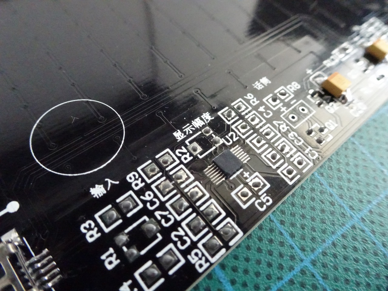
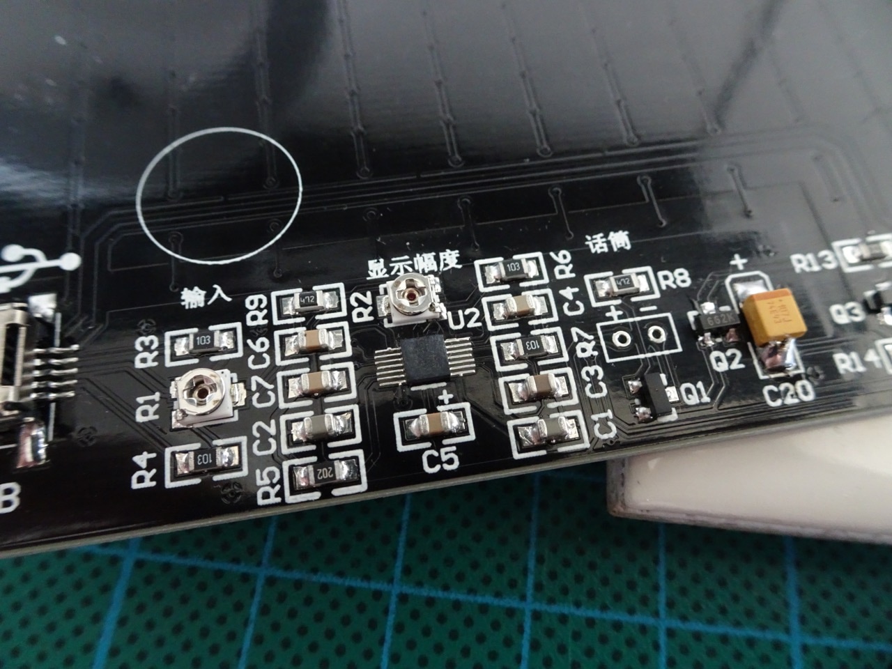
The remainder of the components were rather small SMD parts so I applied solder paste on the PCB pads first, then placed all the components in the right places, and finally used a heat gun to melt the solder paste. From the parts list, I started at the C1 and C2 caps and worked my way down to resistors R12 - R14. Then I placed the R1 and R2 resistors, followed by the Q1 transistor, and finished off with Q2 and Q3 voltage regulators.
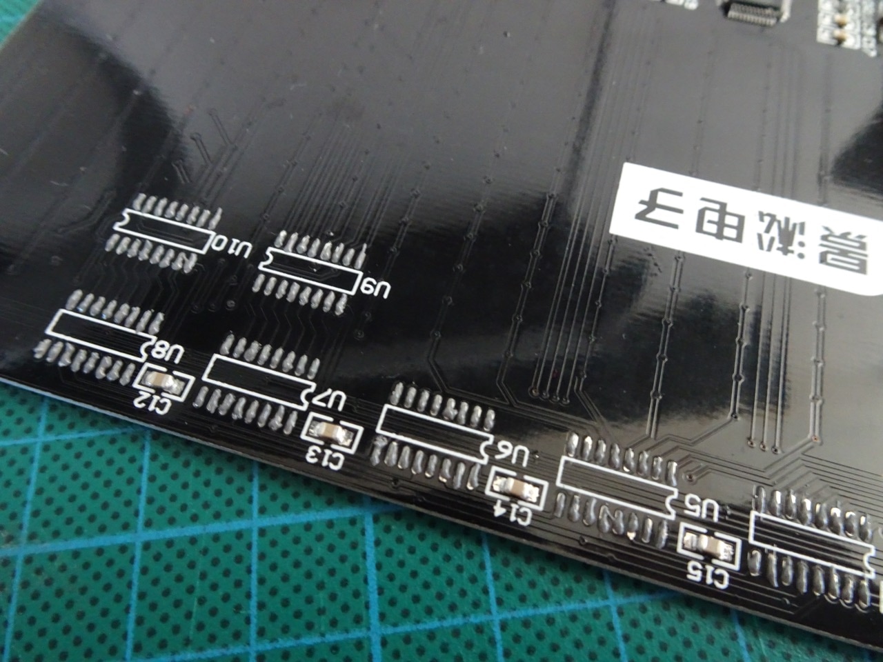
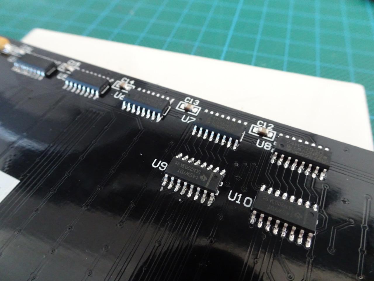
The ICs were next. I used the same solder paste and heat gun method to solder these in place. The order of placing these didn't really matter, but I started at U3 and worked my way down the list to U9 and U10. I also found that I had to use a soldering iron on some of the contacts here - though that was probably more to do with my lack of SMD soldering skills using a heat gun.
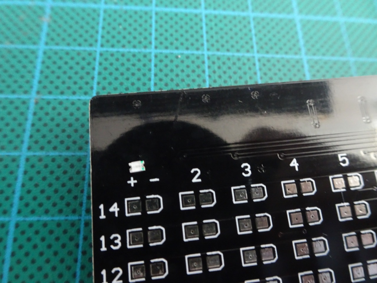
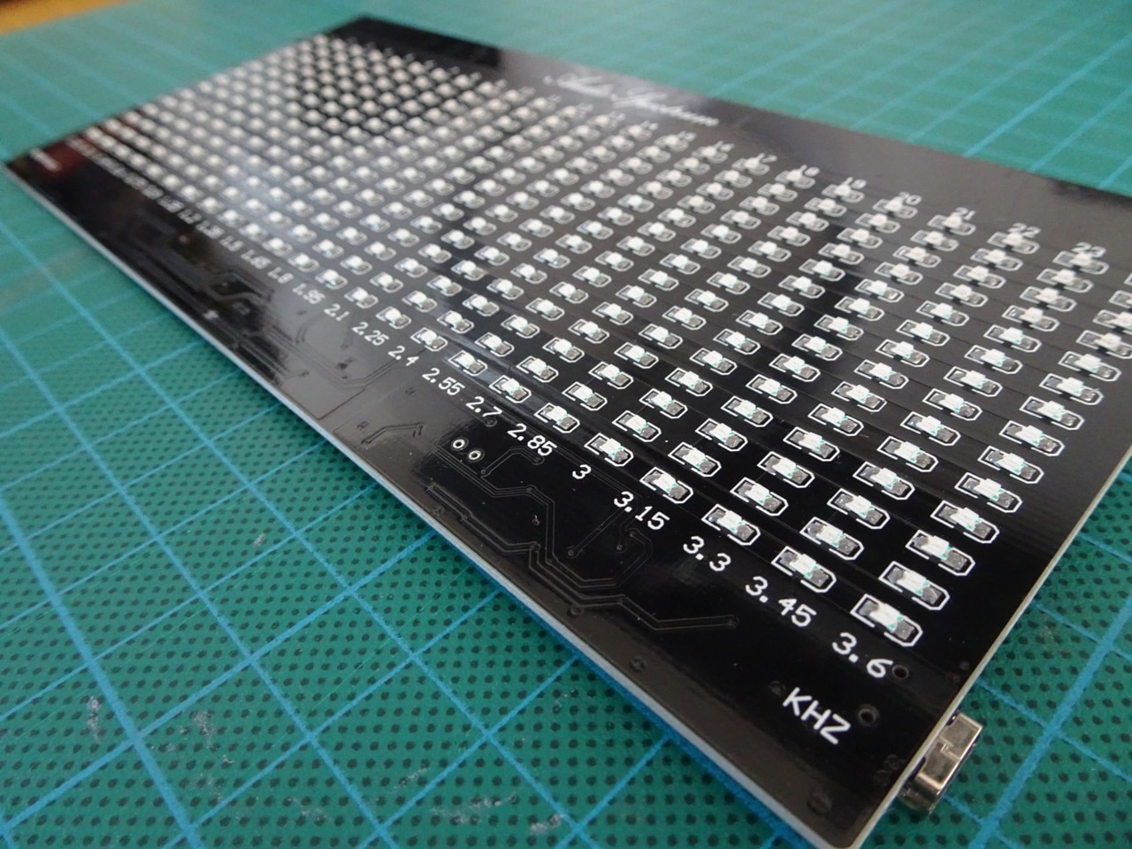
With the rear side of the board finished, I turned my attention to the front side - the side with all the LEDs. There were so many LEDs here! The top 4 rows were red and the rest blue.
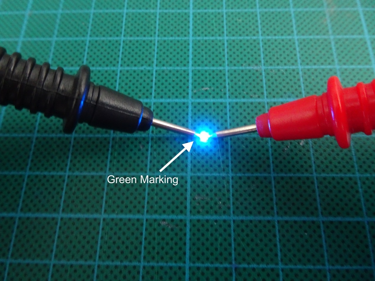
The placement of the LEDs was marked on the PCB in the top left corner. The negative side of the LEDs was the side with the green stripe marked.
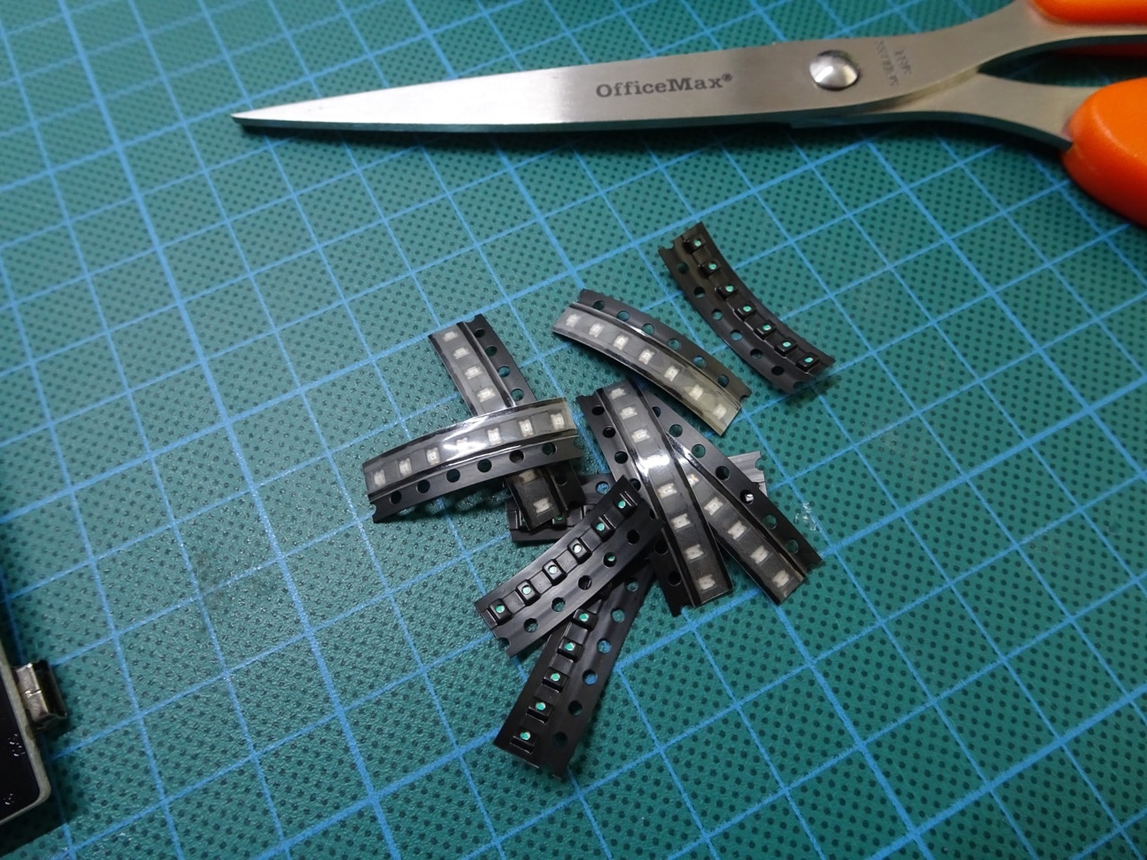
I applied solder paste to all of the pads on this side of the board next. This was definitely an exercise in patience! I also found it easier to cut up the LED roll into smaller strips before cutting them open.
I tried using a heat gun on this side but didn't have much luck so decided to switch to a normal soldering iron. The applied solder paste melted well and eventually I had all of the LEDs soldered in place.
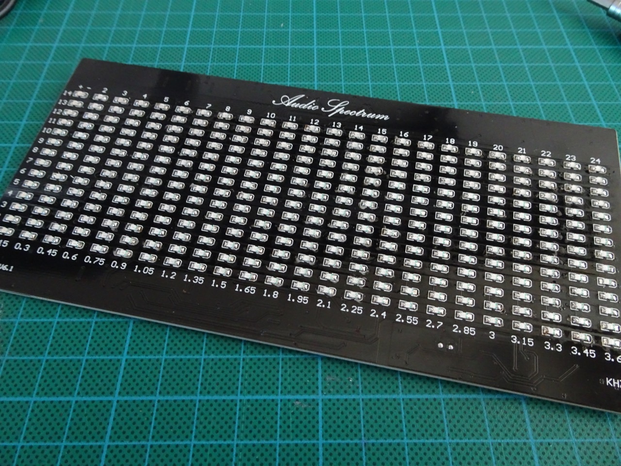
I wasn't sure about the polarity of the microphone and it seemed to work either way to I just soldered it in. There was no clear marking for the microphone on the PCB, just a rectangular box with a plus and minus sign under the R8 resistor.
At this point I decided to test the unit out. It worked!
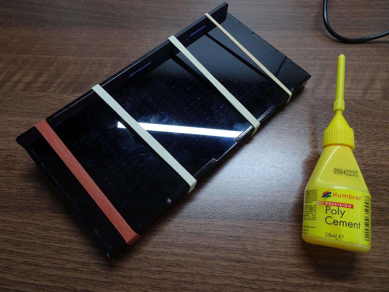
Case assembly was next. There were some rubber spacers that had to be placed on the rear of the PCB - this was so that the acrylic didn't cave in on the board. All of the acrylic pieces had to have their protective paper removed first and then I used Poly Cement to bond all of the plastic together. Rubber bands came in handy to hold the pieces in place while they dried.
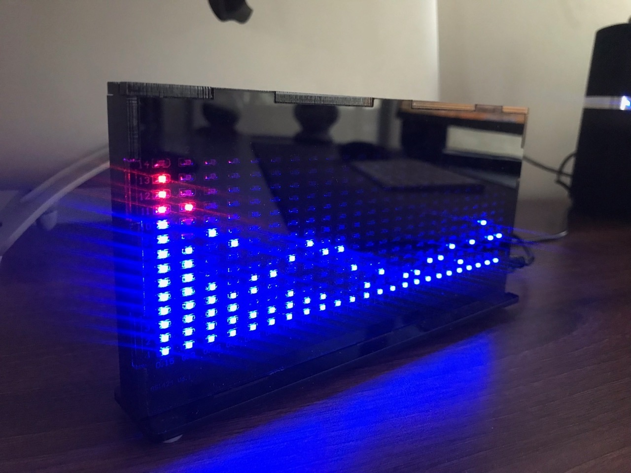
...and that's all there was to it. As I said, the unit looks nice, it has a few different modes of operation for the spectrum analyser - I like the maximum falloff mode the best. Microphone input is rubbish, but line-in works really well. When using microphone input I found that even when there was no sound, the lower frequency bands were picking up some noise, no amount of adjustment of the potentiometers seemed to help here. Still it's a nice unit and a cool kit if, especially if you want to practice SMD soldering!
-i
