These are prototype boards and split into two on purpose. After I verify that these work I will make a single interface board for the LCD module. Both boards were ordered from OSH Park.
So these are the boards...
The LCD breakout board has a few issues and doesn't actually work, I need to update it to make it functional.
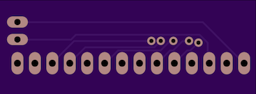
The LCD breakout board is a 'dumb' board. It pretty much just connects the LCD module to pin headers for easier connectivity while prototyping. Some of the pads and pins are connected together to reduce the number of headers required e.g. multiple ground pads break out to a single pin header.
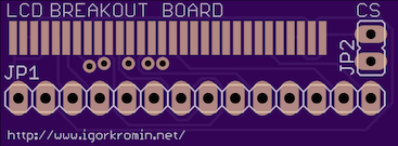
The schematic is straight forward too. JP2 is a CS (cable select) jumper to enable writing to the device without having to connect pin 3 to a digital pin on the MCU. If the jumper is shorted, the LCD will always be in 'write' mode i.e. it will accept commands. The same functionality can be achieved by setting pin 3 to high if connected to a MCU.

The power and level shifter board is more interesting. Since the LCD requires 2.8V signalling, the voltage outputs from a 3.3V Arduino must be converted. I used a pair of 74HC4050D ICs for this task. These only handle high-to-low conversion, but since I didn't require the ability to read from the LCD these chips were fine. The LCD breakout board is not set up to allow reading the LCD anyway (it is an output device after all).
The power board includes an LDO voltage regulator which can accept voltage input between 2.8V and 5.5V and output 2.8V @ 300mA. This is used to power the level shifter as well as supplying several pin headers with the 2.8V output.
In addition to the power circuitry, there is a buffered LED driver circuit that can be controlled via a PWM signal to control the backlight LED intensity of the LCD.


These are my picking lists for each board...
LCD board:
- 1x 14-pin header
- 1x 2-pin header
- 1x 2-pin jumper
Power board:
- 2x 12-pin header
- 2x single pin header
- 1x 2-pin header
- 1x 4-pin header
- 2x 74HC4050D
- 1x RT9166-28GVL
- 1x BSS138N
- 2x 4.7uF caps
- 1x 10k resistor
- 1x 100ohm resistor
Now I just have to wait until it all arrives so I can put it together and verify that it actually works.
-i
