You can get the kit from Bang Good: DIY Aurora LED Color Light Cube Chromatography Glass Clock Kit
At a later time I hacked this kit and replaced the speaker by a LED to stop it from making the loud beeps on the hour. Read this article to find out more!
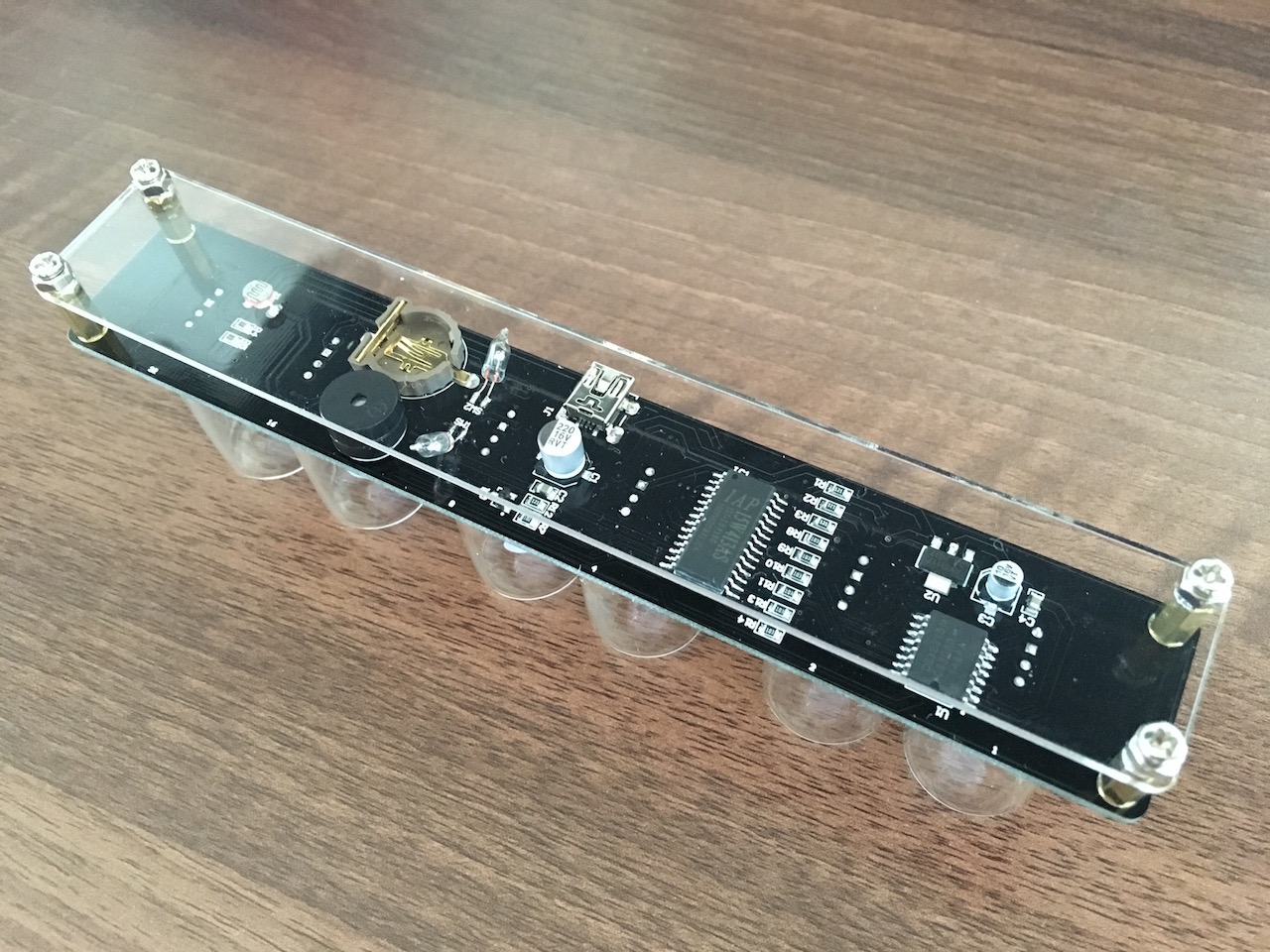
This is what the assembled product looks like.
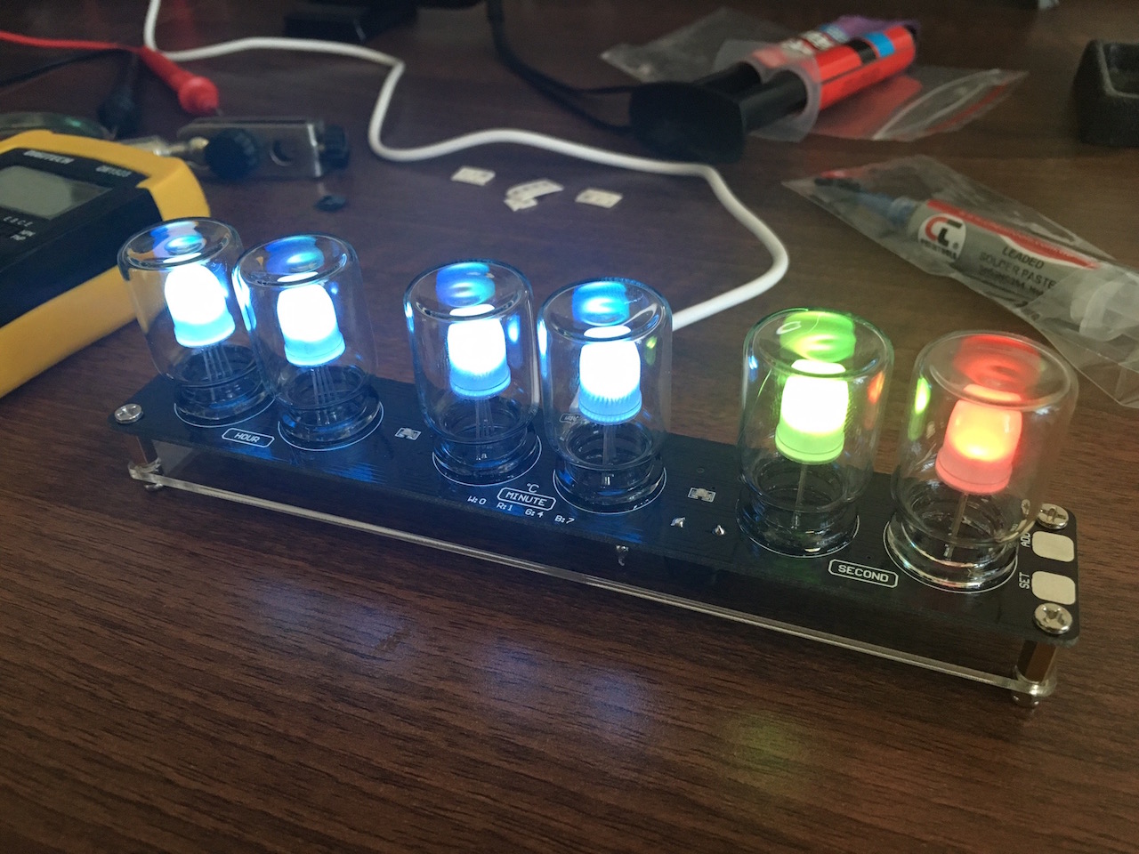
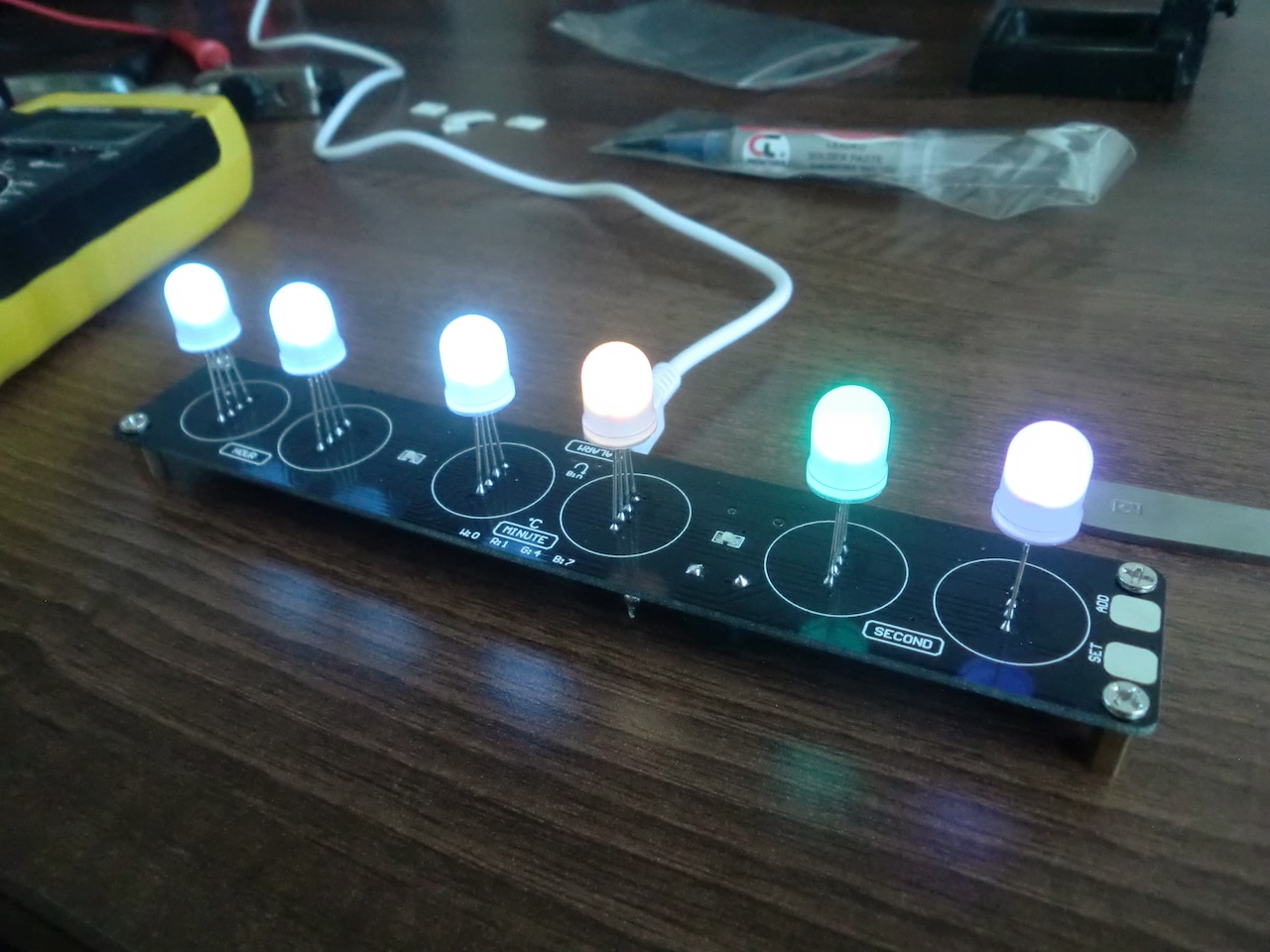
In case you are wondering what this is, it's a clock! Each of the numbers is represented by a colour with the following table:
Numbers and Colours
0 - White
1 - Red
2 - Orange
3 - Yellow (greenish yellow)
4 - Green
5 - Greenish cyan
6 - Blueish cyan
7 - Dark blue
8 - Purple
9 - Pink/Magenta
So lets see how this this is assembled. First thing you will notice when you get this kit is it has no instructions. Nothing. You're on your own, unless you go back to the Bang Good website and look through the item description that is. There is an inconspicuous link to an instructions PDF, which seems to have been ripped off another website. In case you are looking for that link, it's this: https://copy.com/vlTwwjUJwlVa7Ojy.
Update (5 January 2019): The original author of the kit reached out to me to share the official instructions PDF, so here it is: http://www.ledsales.com.au/pdf/Colour_clock_instructions.pdf.
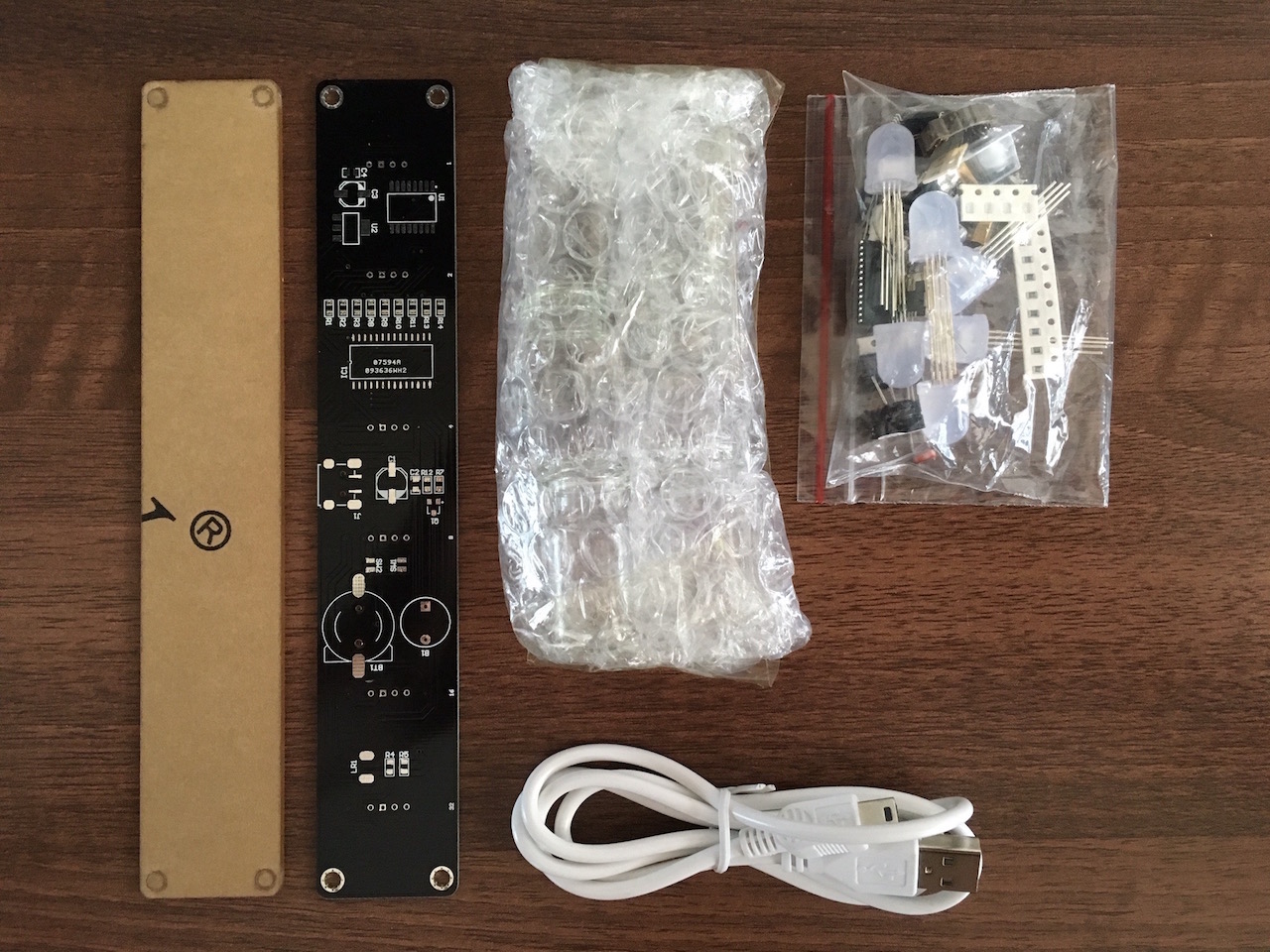
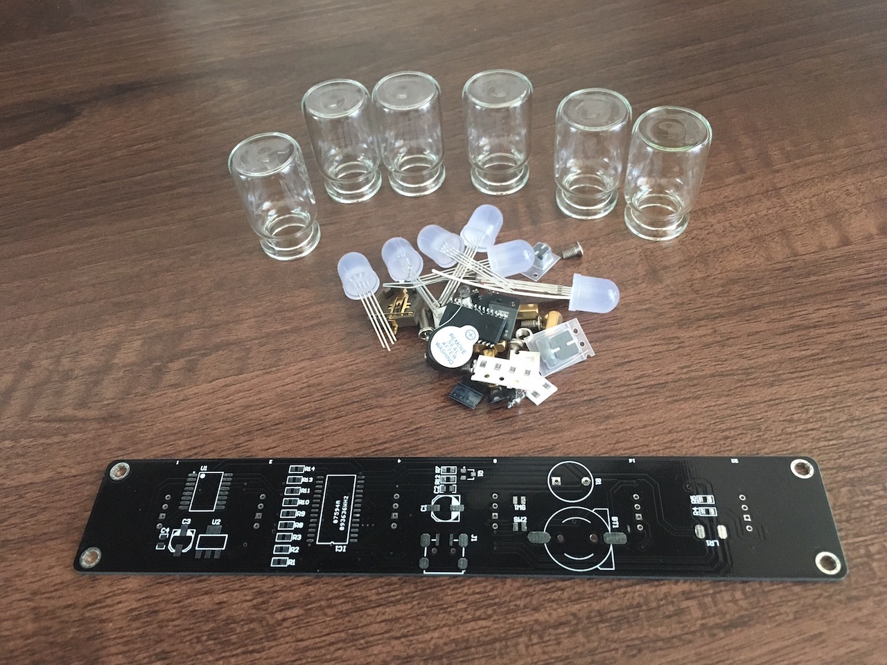
When you unpack the kit, you get the main PCB board, an acrylic base plate, mini-USB cable, glass tubes and all the components packaged together in a zip lock bag. The board virtually has no through-PCB components, most of the parts are SMD type. Naturally the components come in strips in the usual SMD style packaging. I was surprised that the ICs didn't come in any sort of package, they were just thrown in on their own.
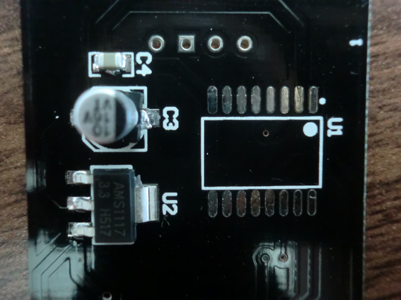
The instructions PDF is a bit skimp on information, but basically what you want to do is solder on the USB connector, followed by the can capacitors (the board marks the orientation clearly), then all of the SMD components (resistors, capacitors, voltage controller, transistor, battery holder) and finally the ICs can go in last. Of course since this is all SMD soldering you can apply the solder paste and then heat it up in one go, up to you!
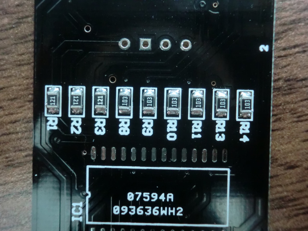
I found the lack of documentation on which resistors were which a bit annoying and had to use this SMD resistor code calculator to figure out a few values. In particular these were the missing values: 1k (102) and 10k (103). The SMD capacitors are not marked, they're they yellowish looking components.
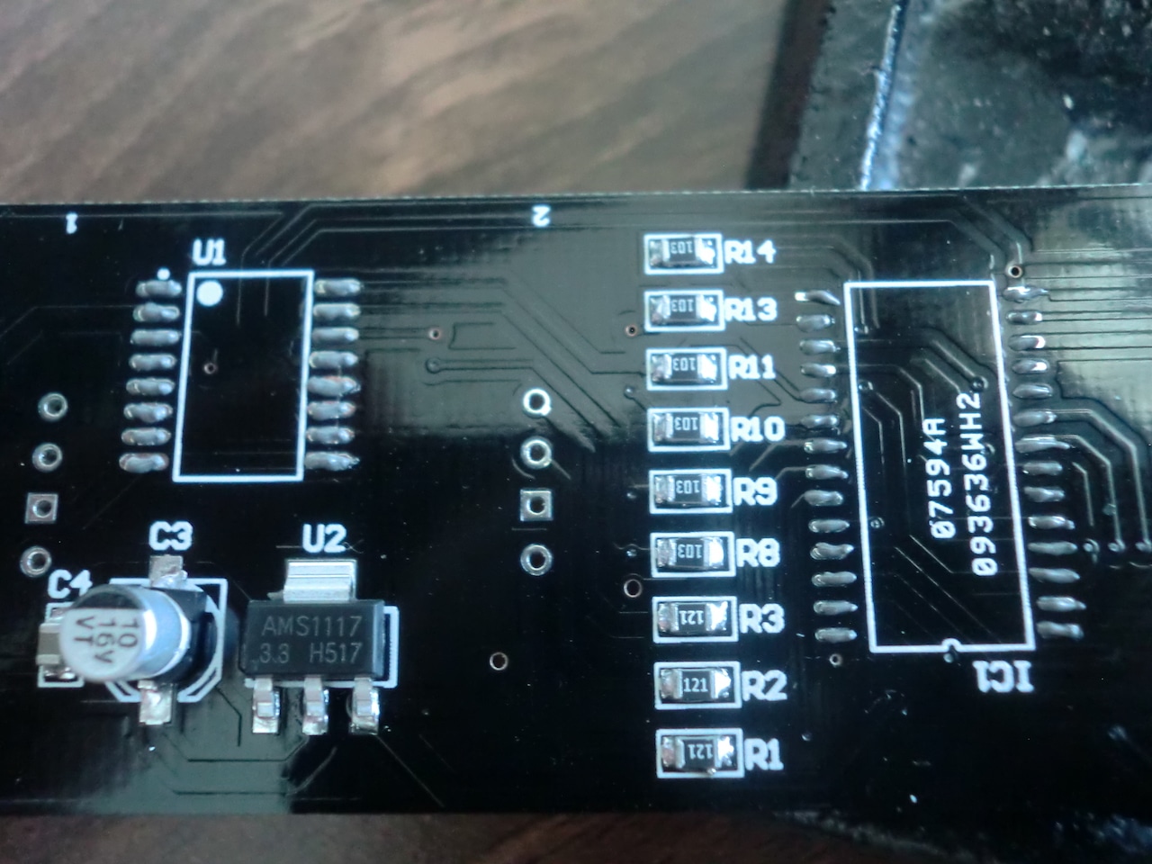
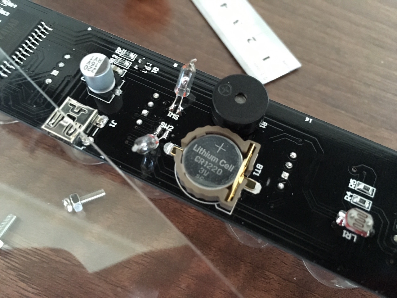
Here are some high-res photos of the soldered-on components to show which ones should be placed where.
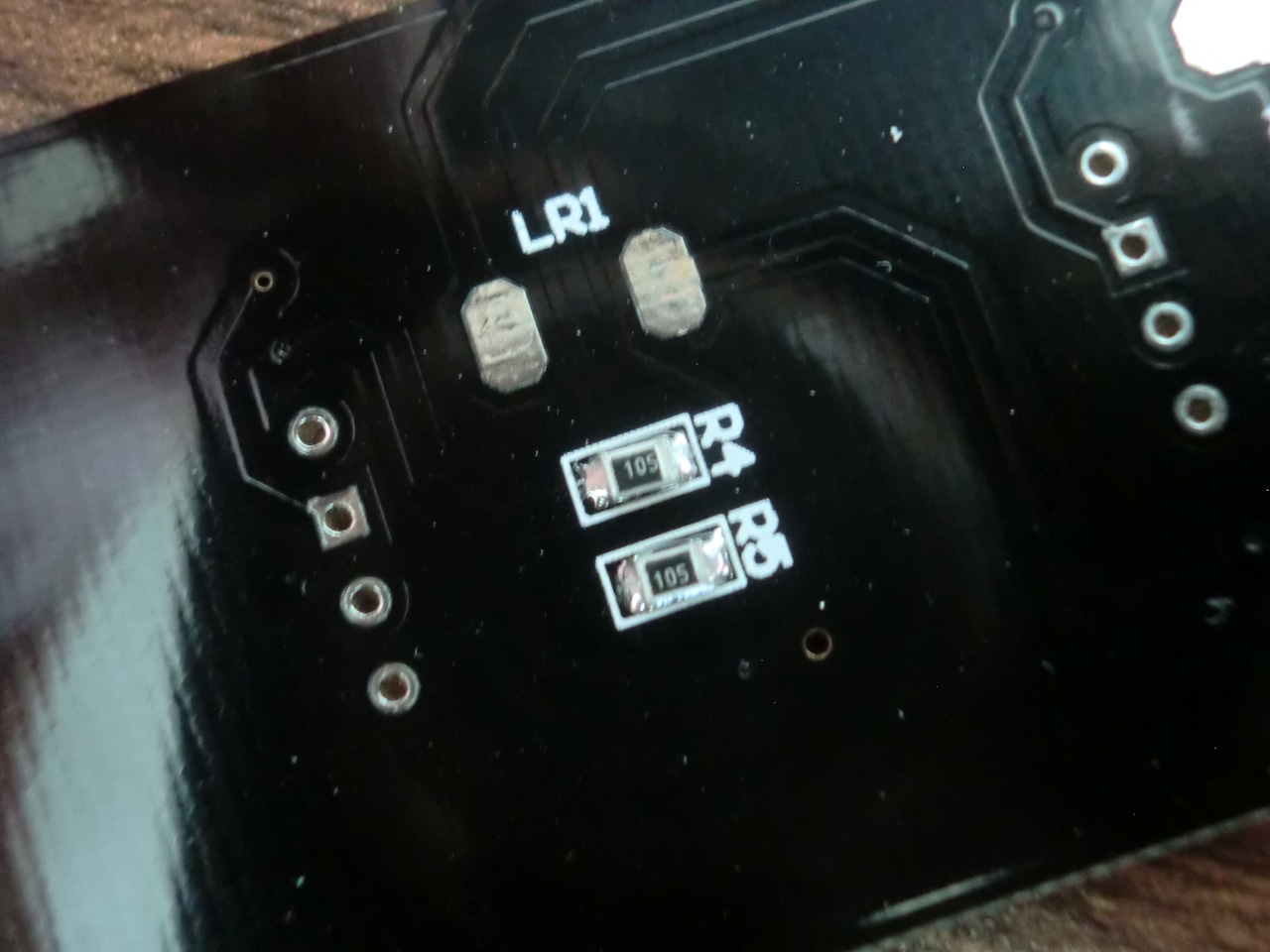
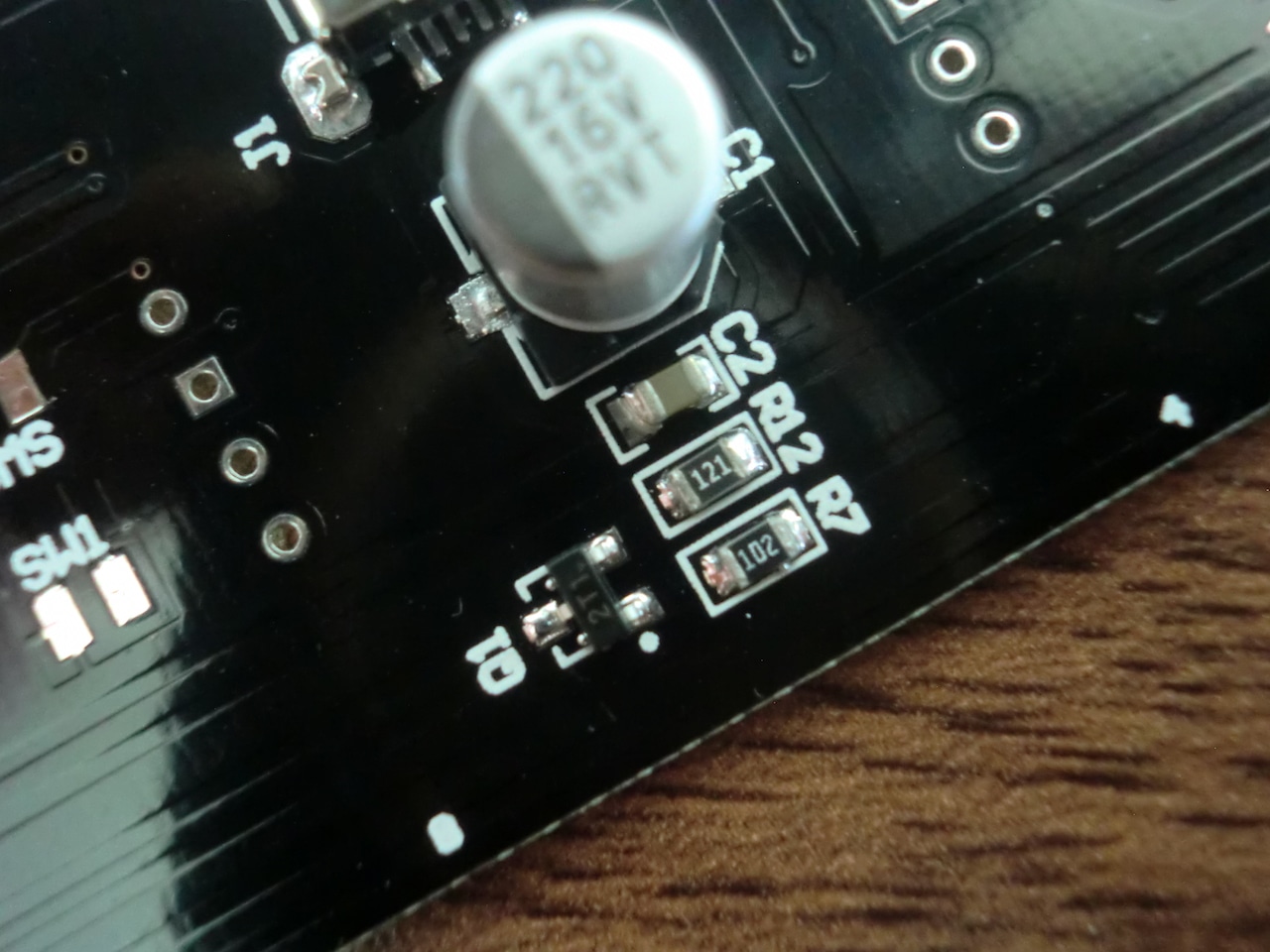
The ICs have quite a few pins so be careful.
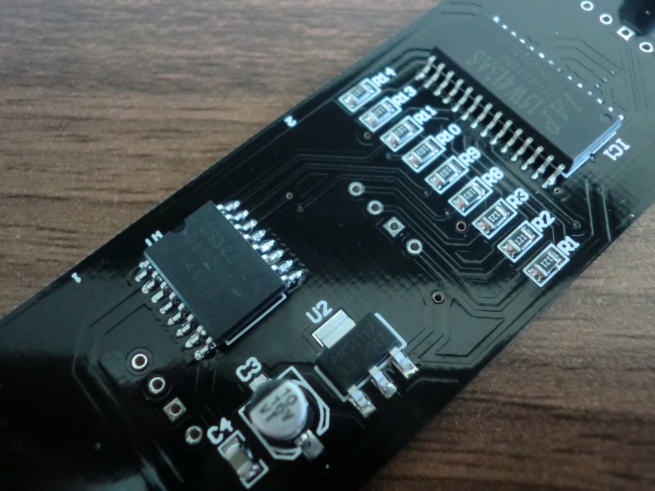
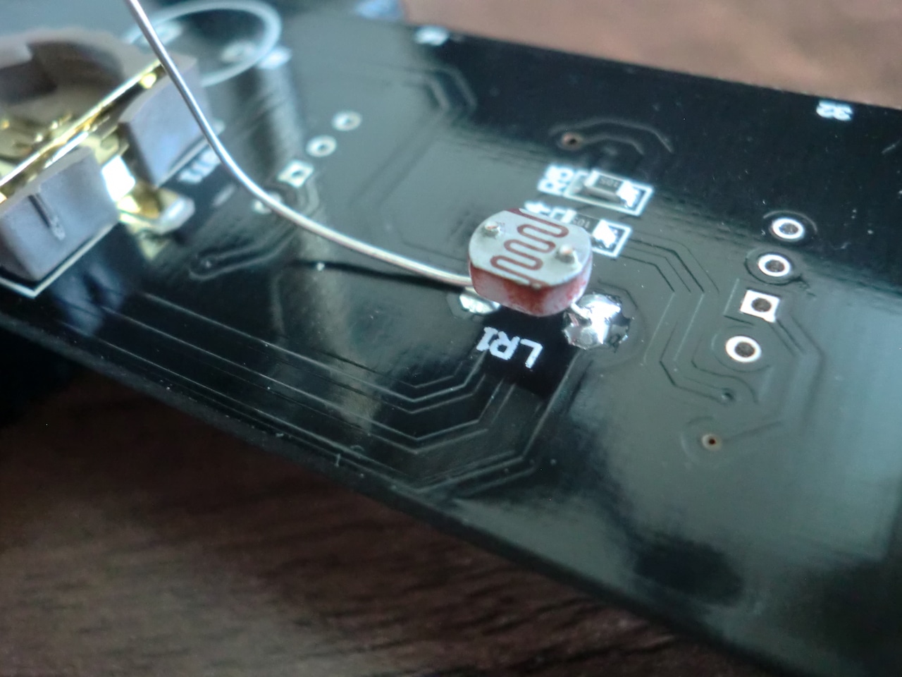
The photoresistor was a bit tricky to solder on since there is no hole in the PCB for it. I ended up clipping one of the legs short and soldering that on first, then the second leg was clipped and soldered on in a similar fashion.
After this I put the speaker in, note the orientation. The Mercury switches went in after this. These are also quite tricky to get right in position since they're surface soldered. The best way I found was to straighten the legs out so they line up to the pads and solder them on flat, then bend the switch into it's 45 degree position.

At this point the device can be tested by plugging it in and touching the induction switches on the PCB, if you get a sound from the speaker, you're all good to go on. Unplug the USB cable and continue.
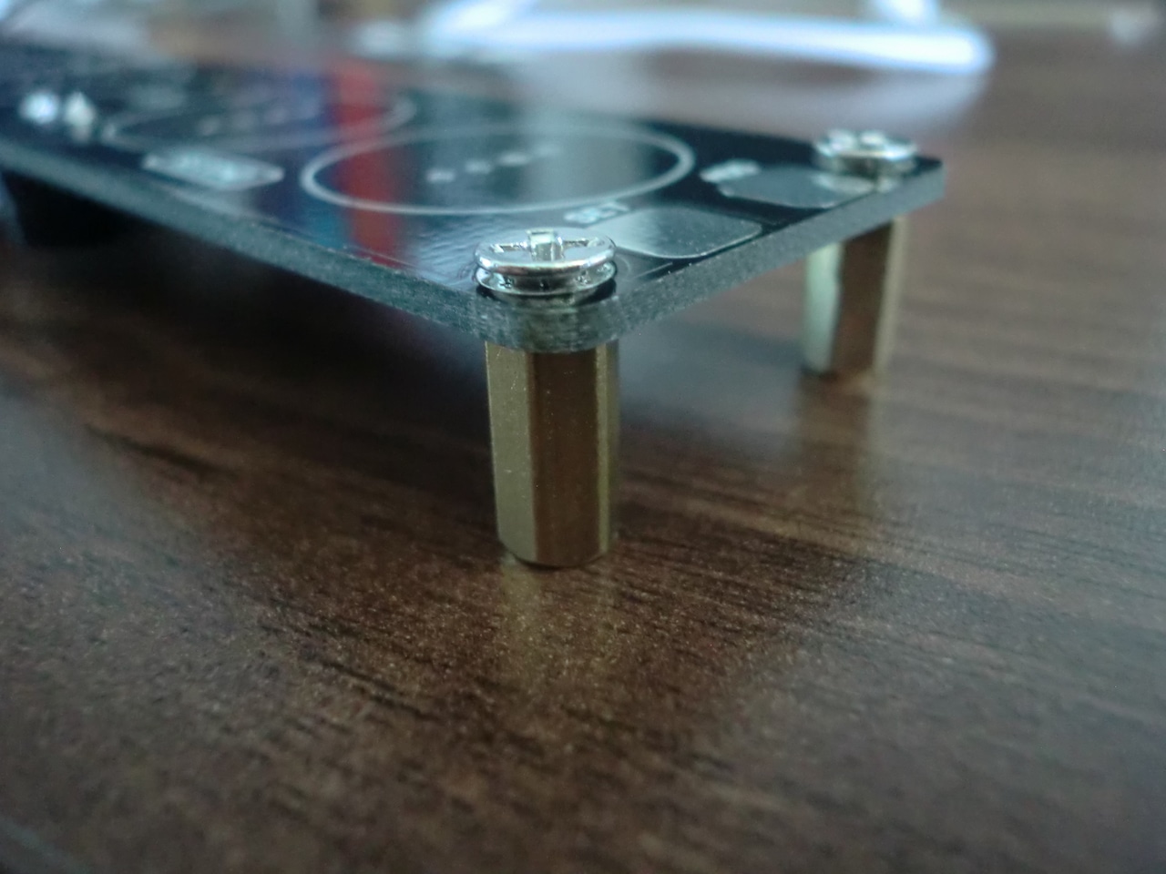
This is also a good time to fit the PCB stand off mounts.
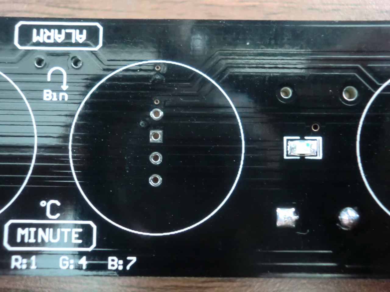
The LEDs were next. First the SMD LEDs should be soldered on. Note the orientation of the green dot, it should be on the right hand side when the board is oriented towards you. The RGB leds go in next (longest leg in pin hole marked with a square).
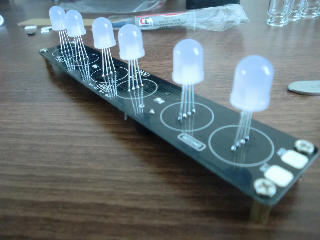
Before fitting the glass covers I wanted to make sure the LEDs were all working, so I did another test run, it was successful...
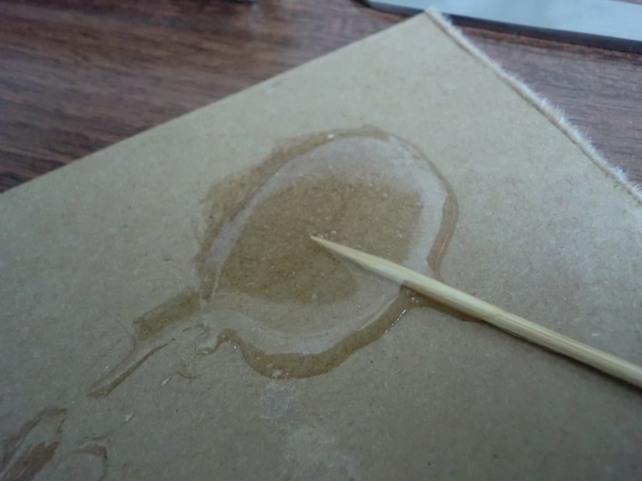
Instead of using a hot glue gun I decided to use 5-minute epoxy resin to fit the glass covers. It dries clear so was a good option.
Once the covers were in place and epoxy was dry, the battery could go in and the acrylic plate was mounted into place. The kit didn't come with a battery and it was not labelled what type you actually needed. I worked out the type that's required is a CR1220 3V button cell.
...and that's the end! It took me close to 3 hours to assemble the kit because I had to find out the values of all those SMD components, hopefully anyone reading this will be able to do it quicker by looking at the photos in this article.
Here's a short video of the clock in action...
♣ Open image gallery
for this project for more photos.The kit is available online here: DIY Aurora LED Color Light Cube Chromatography Glass Clock Kit
-i
