This article is not a replacement for the official instructions but a supplement since the official instructions do not show an incrementally populated PCB. Get the official instructions here.
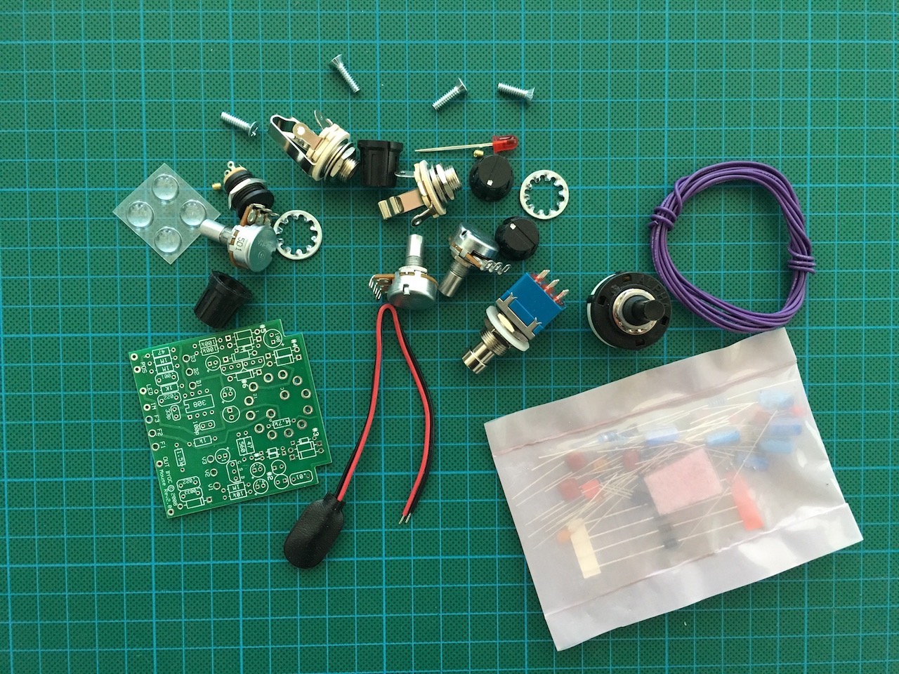
This is what was included in the kit. The bulky components were in the main package and the smaller electronic components were sealed in a smaller bag inside.
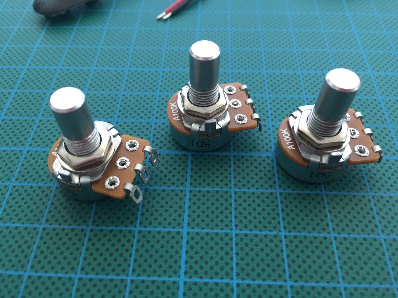
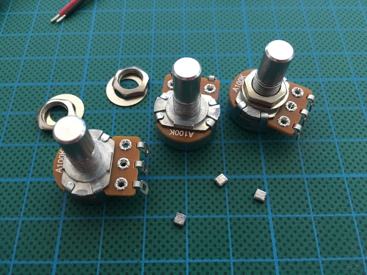
I removed the posts off all the 3 pots first. The posts are really easy to snap off using pliers.
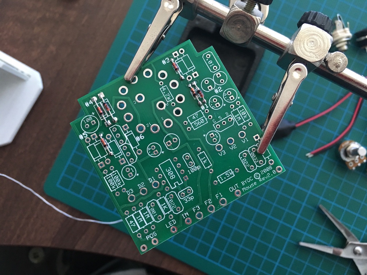
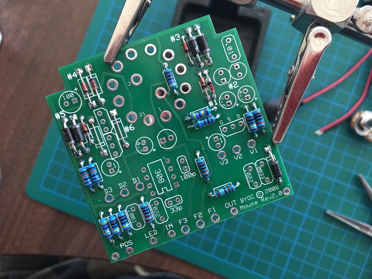
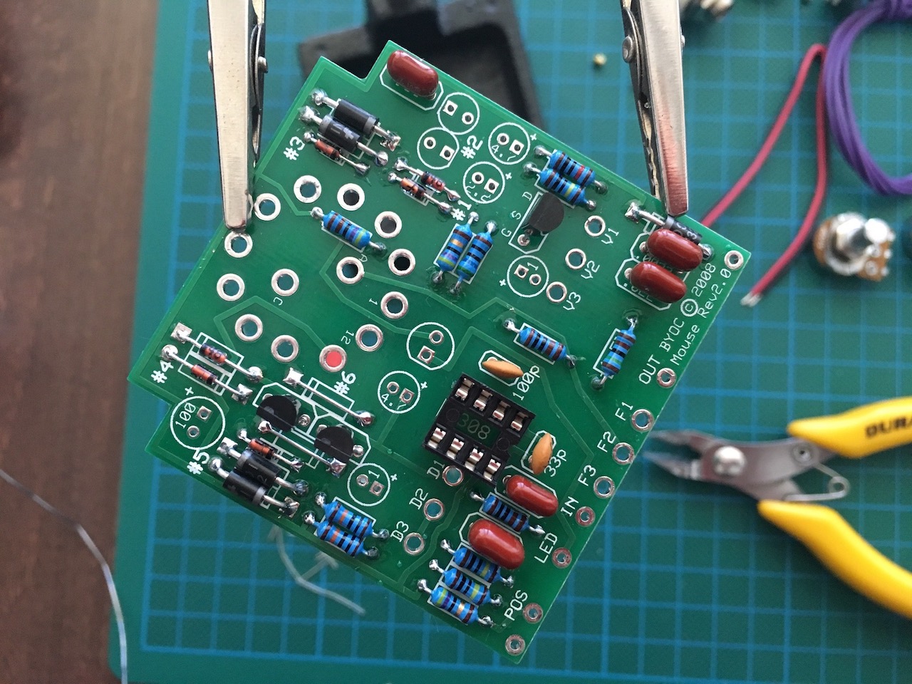
The small glass 1N4148 diodes went in first. In my typical fashion, I top soldered the components first, then snipped their pins off and soldered them from the bottom. This is not strictly necessary but it does make for a more professional finish.
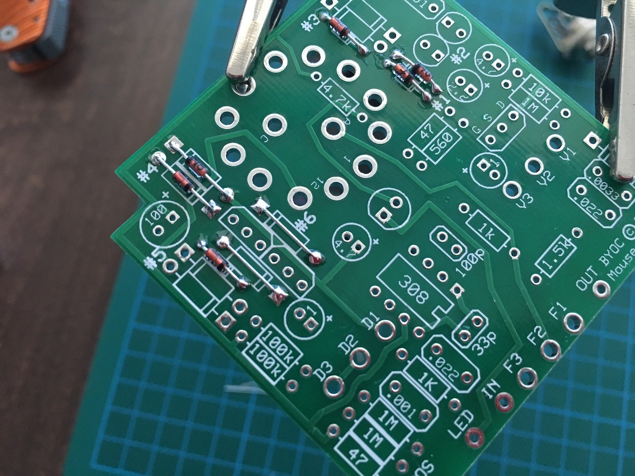
After the diodes were in, I used some of the snipped off pins for the two jumper links.
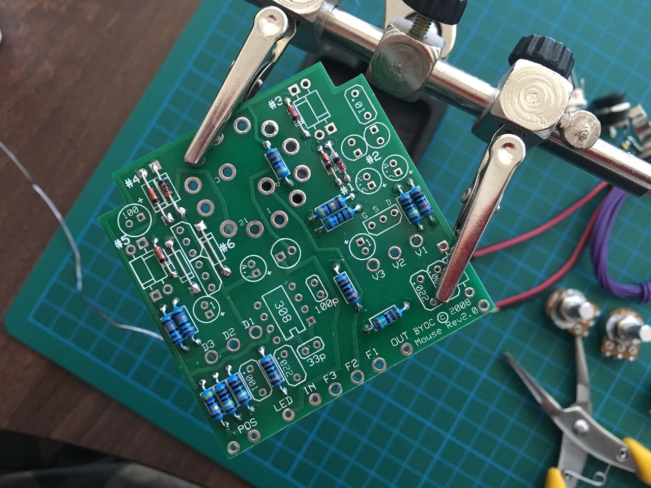
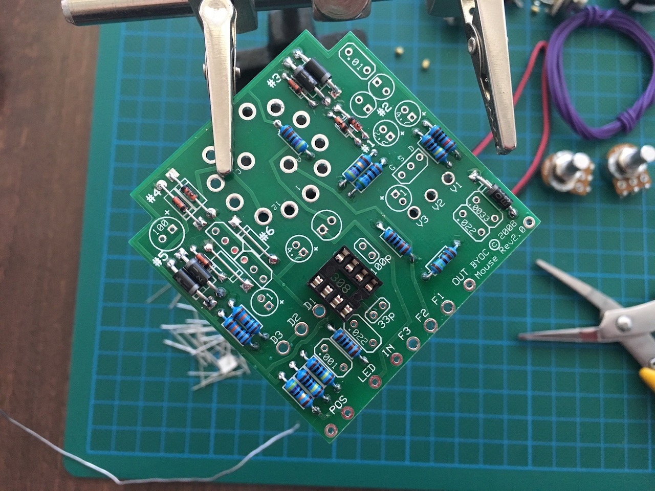
The resistors were in next.
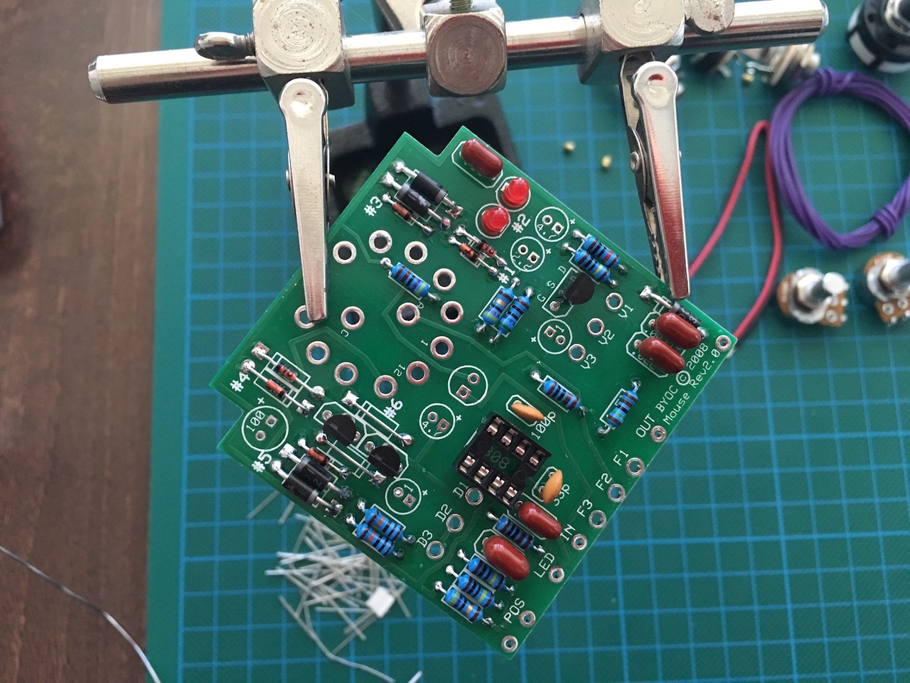
The 1N4001 and 1N4002 diodes were soldered in place afterwards.
The IC socket went in next. It couldn't be top soldered for obvious reasons so to hold it in place I bent its pins to the sides so that it wouldn't fall out when the PCB was turned upside down for soldering.
After the IC socket, the transistors were put in.
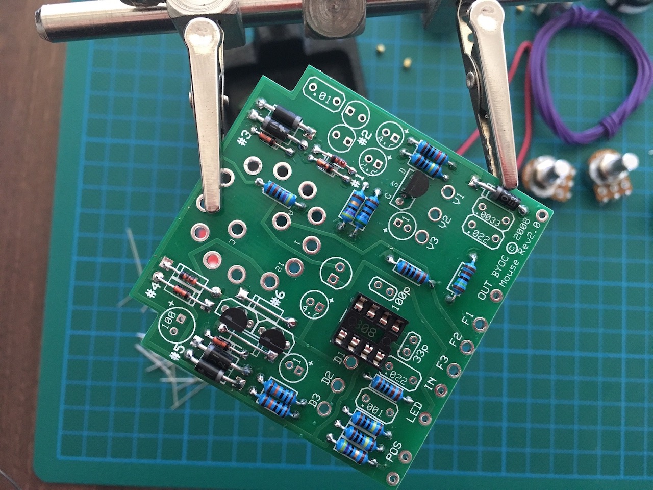
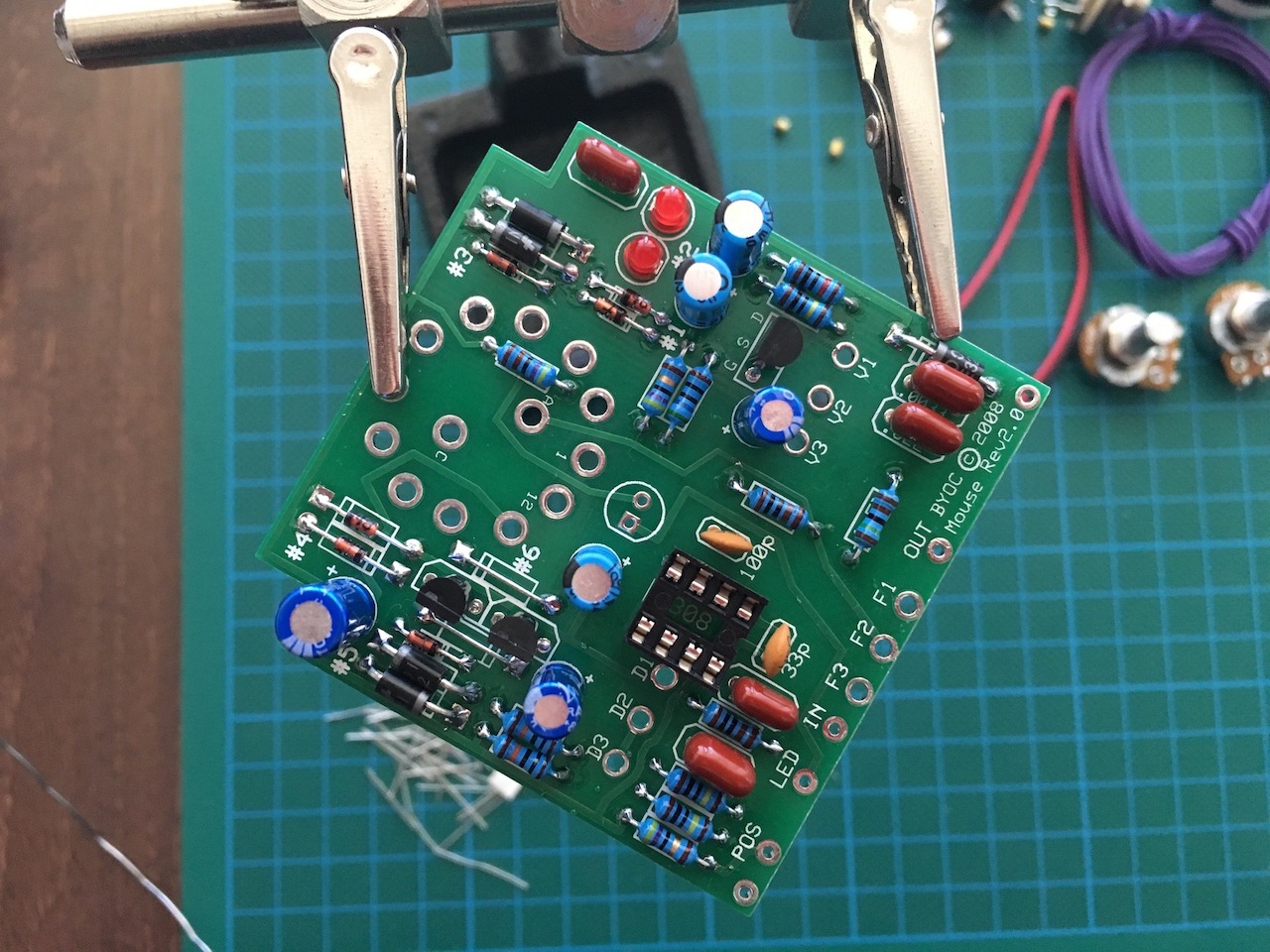
Ceramic capacitors were soldered on next. These could not be top soldered either so I bent their pins out in opposite directions to hold the caps in place. After lightly soldering one of the pins I could straighten the other and solder it in place. Then I finished the first pin by soldering and straightening it out at the same time.
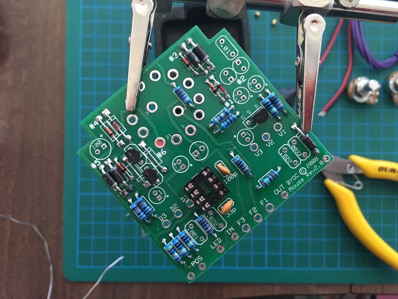
After the ceramics, the metal film capacitors went in.
The two red LEDs were in next.
The electrolytic capacitors were in afterwards.
Last was the rotating switch. Mine was already preset to the correct spot but it is worth checking to make sure that inside the number 6 notch is used. The switch is soldered into the board upside down and it doesn't matter which way around it goes.
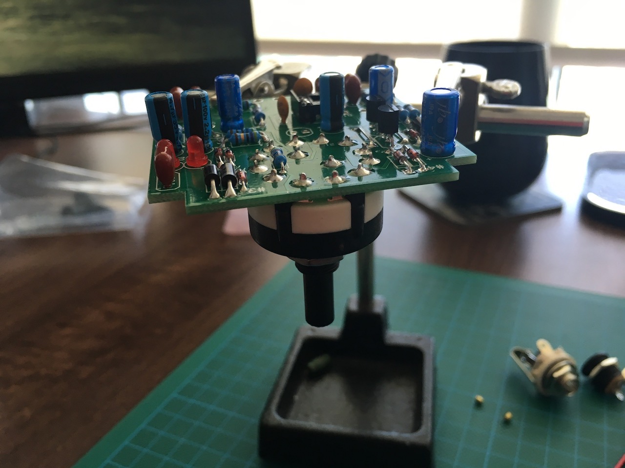
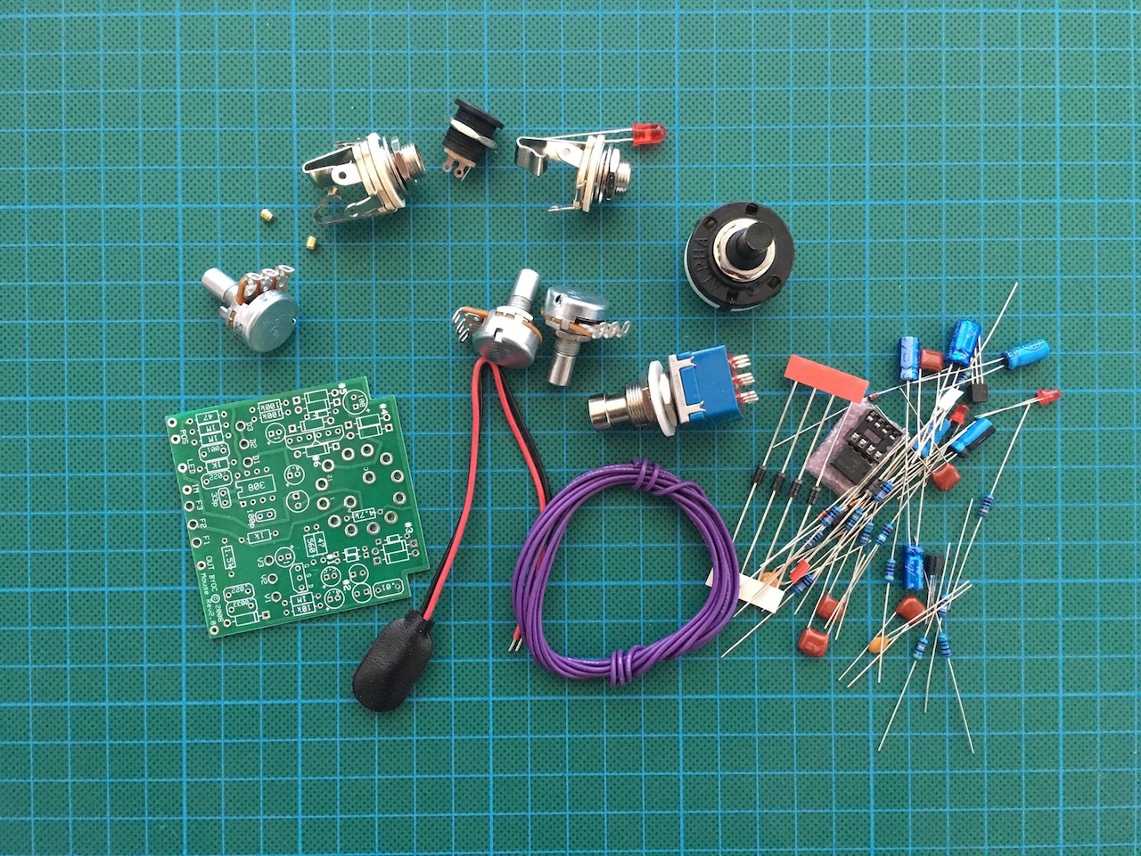
That was it for that part. I had to make progress with the case next. The components below are what I had left over waiting to go in after the case painting was completed.
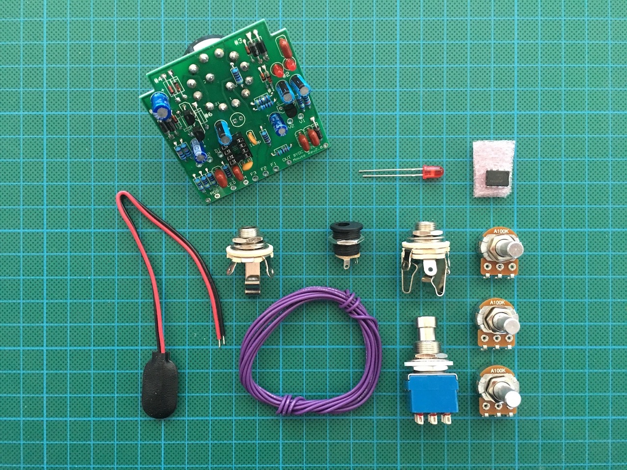
At the moment I am on my 3rd attempt at painting the case, hopefully this time I'll get it right! Stay tuned for updates and completion of this project.
Update: The second part of this article is available to read here.
-i
