This is the second part of the construction of this pedal which includes the final wiring and fitting of all of the external components like the foot switch, rotary switch, plugs, etc.
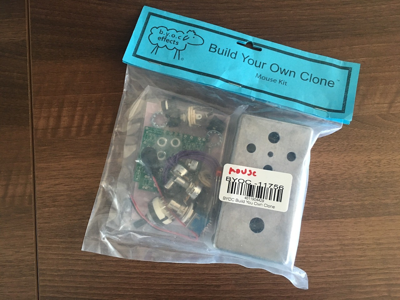
First, a small step back - this is how the BYOC Mouse kit came originally. The pedal housing was bare metal and unpainted. All of the components to build the pedal were included, however no instructions were present as they were available online.
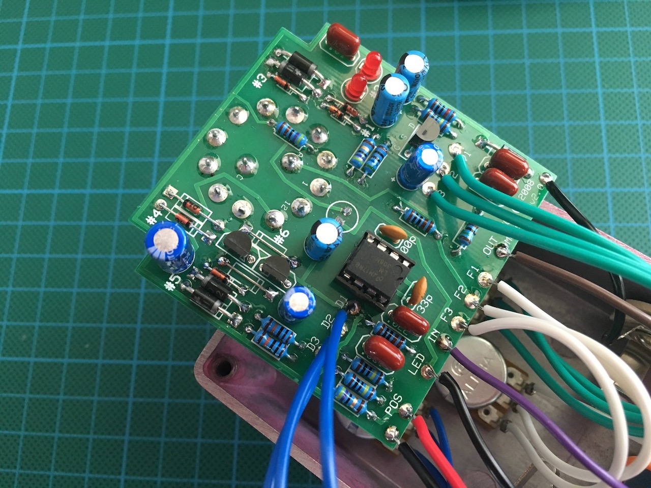
So lets get to the fun part. At this point I had the PCB assembled and the rotary switch fitted. Next up was aligning the LED and soldering it in place. This was a little tricky because the PCB didn't align perfectly to the LED hole in the case. To counter this I had to bend the pins on the LED to make it match up better. Further, the LED didn't stick all the way through the hole so it took some fiddling to align it.
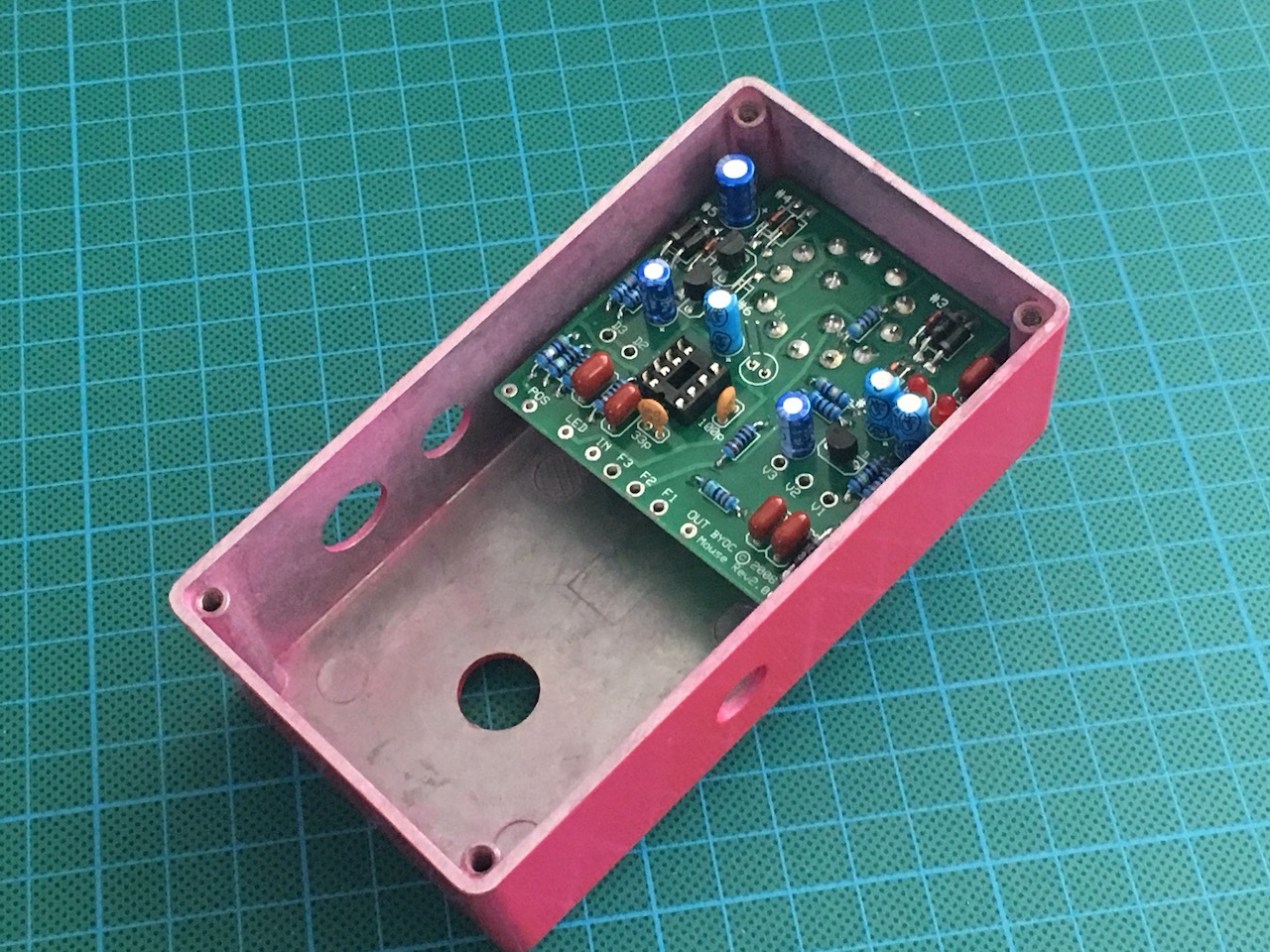
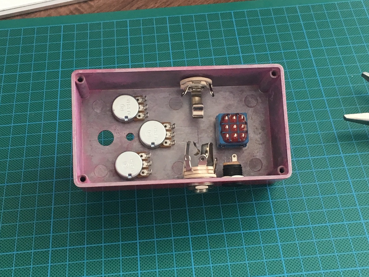
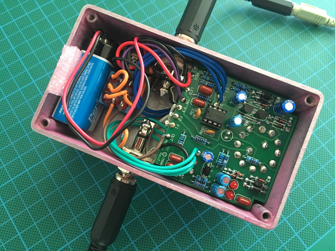
With the LED and the rotary switch aligned I removed the PCB so that I could fit the rest of the components. This included the potentiometers, 6.5mm sockets, foot switch and the power socket. These were put in place and tightened with pliers.
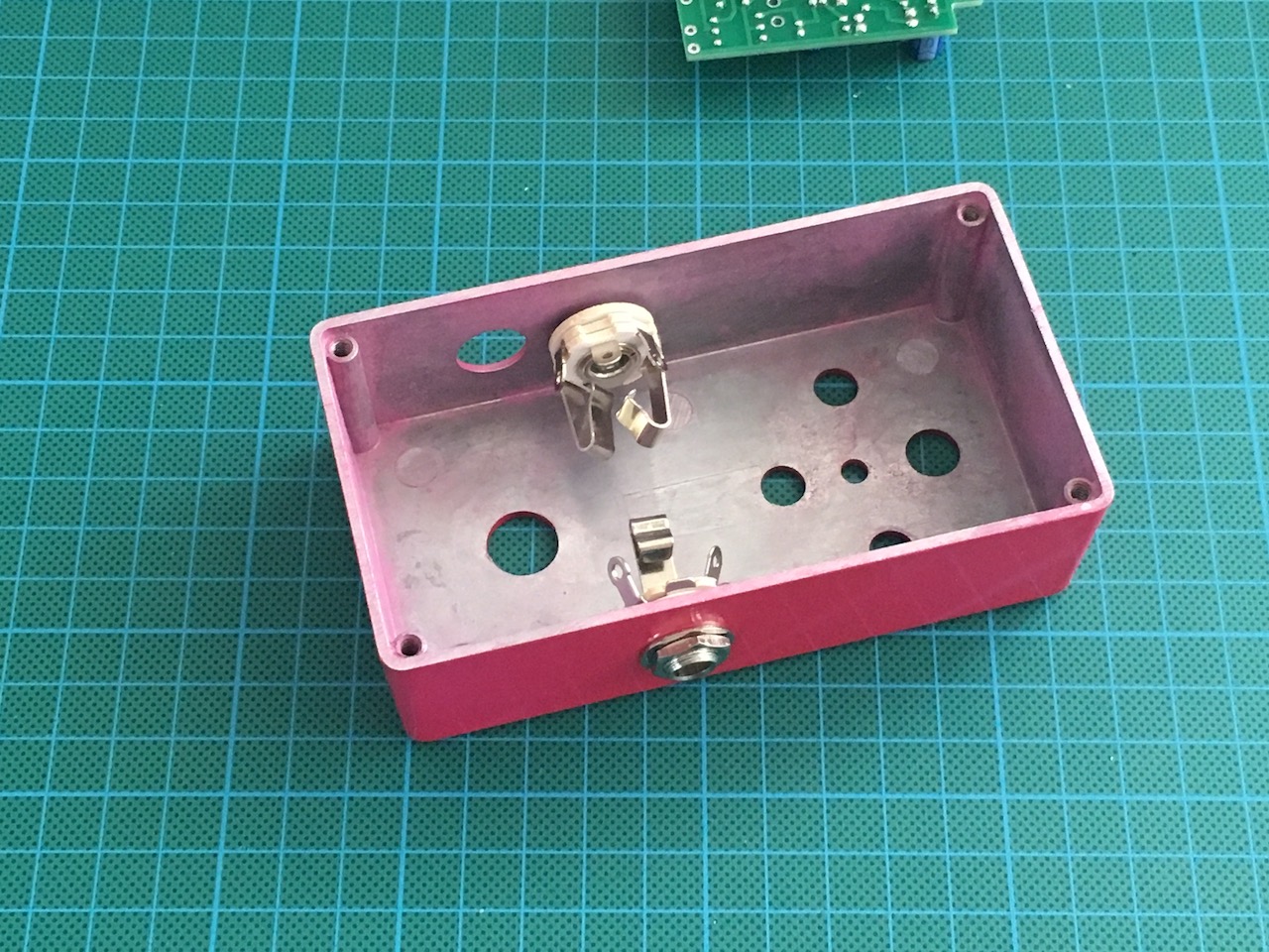
With the external components fitted it was time to wire them up. The BYOC Mouse kit came with a length of wire for this purpose but I chose to ignore it and instead use different coloured wires for each of the components I was connecting. The instructions actually showed different coloured wiring so I went with similar colours. The pots were the first to be wired up because they were going to be covered by the PCB after their wires were connected.

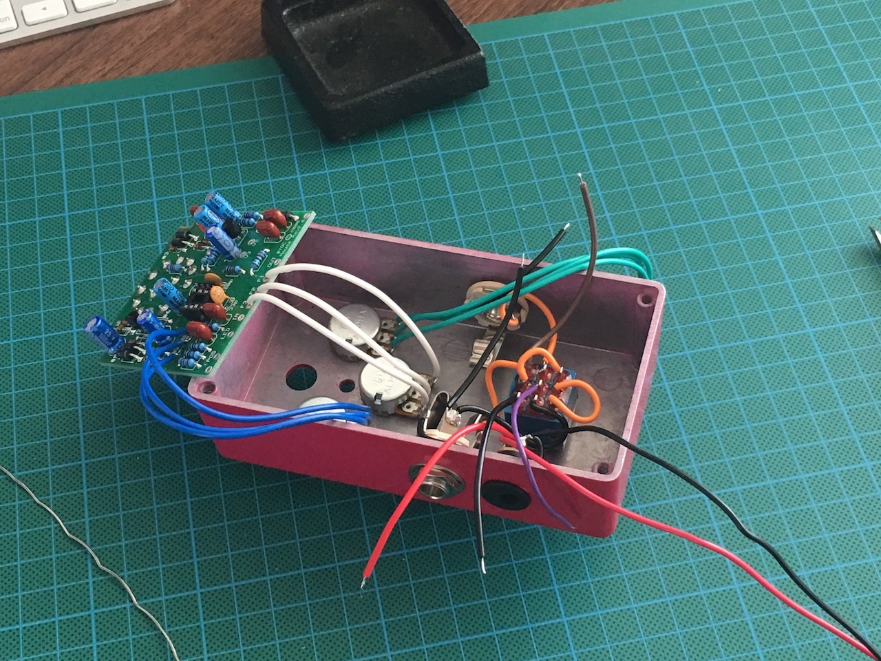
It took quite a bit of time and patience to connect everything, but after using meters of wiring, everything was in place. There was nothing special in terms of getting this wired up, I just followed the colours in the instructions.
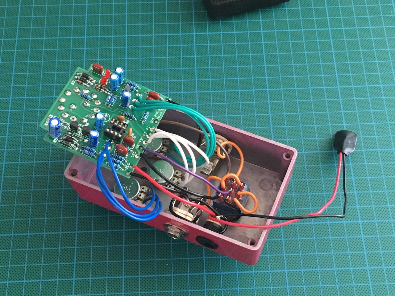
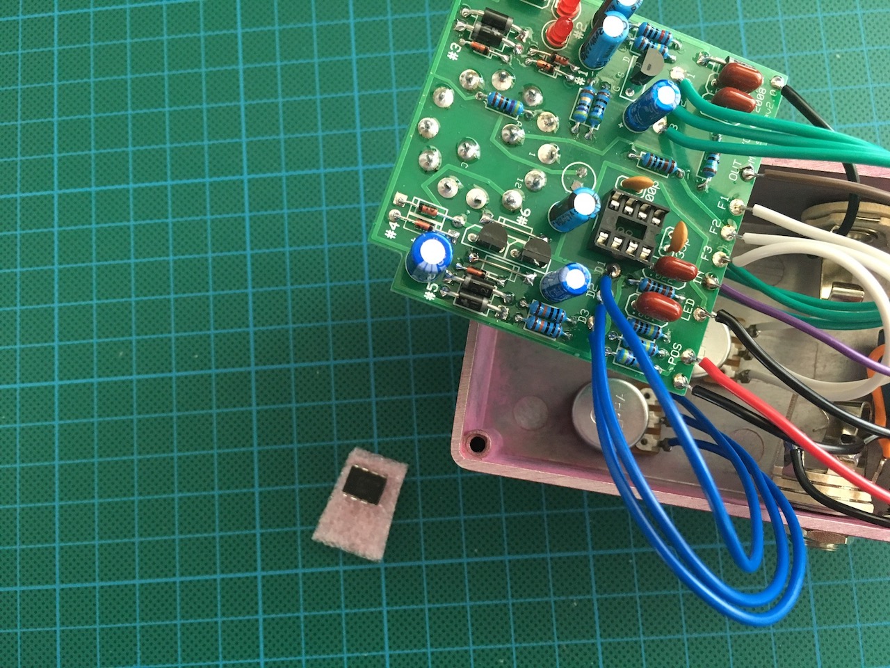
The IC was the last piece to be fitted to the board. My IC had a bunch of bent pins so I had to straighten those out first, after that it slotted into its socket with ease.
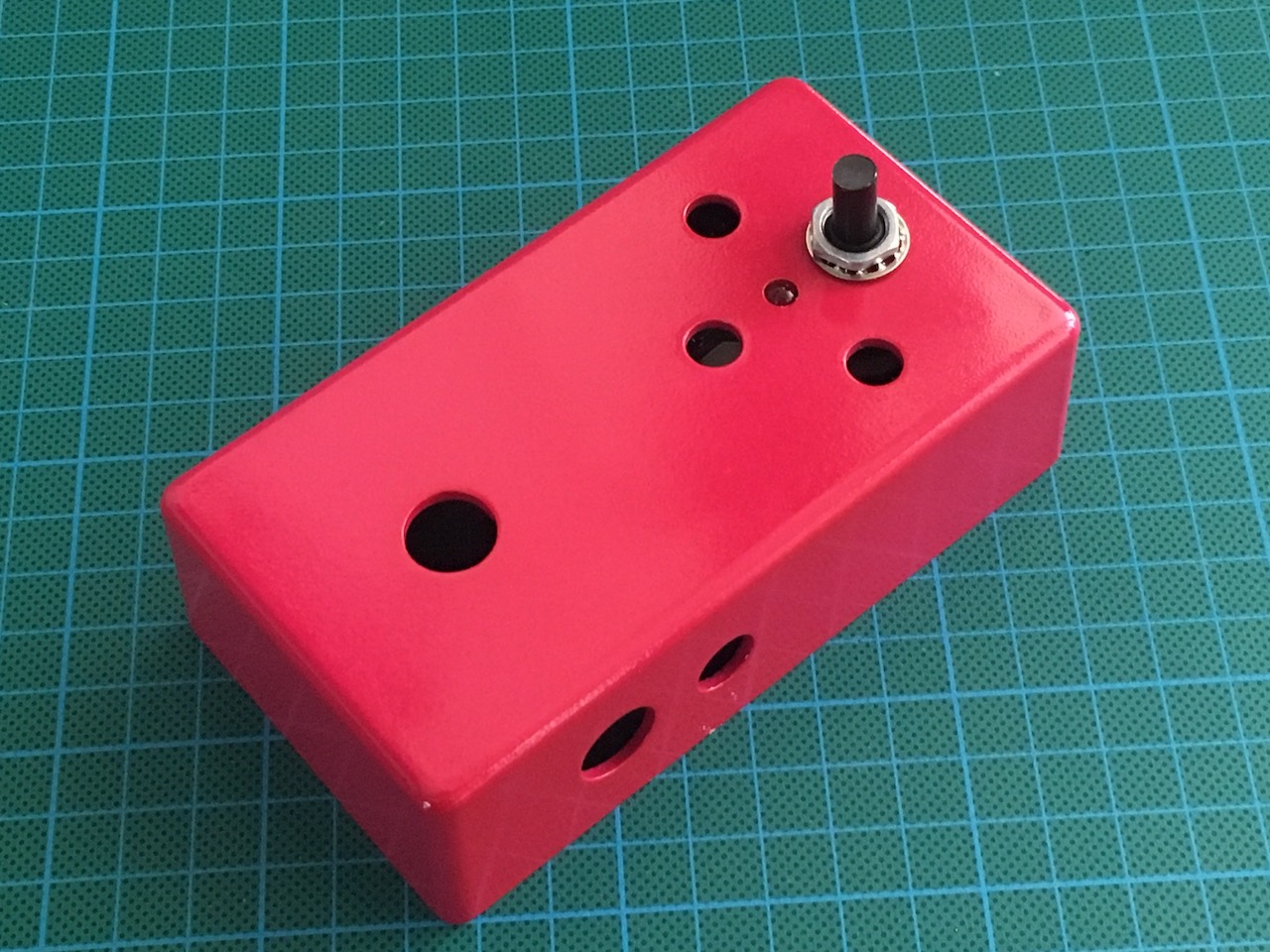
I put the PCB back into the case, screwed in the rotary switch from the opposite side and connected a 9V battery. The battery was initially a bit loose inside the housing so I used the bit of foam that the IC came in to pad out the space. It's very cramped inside this pedal!
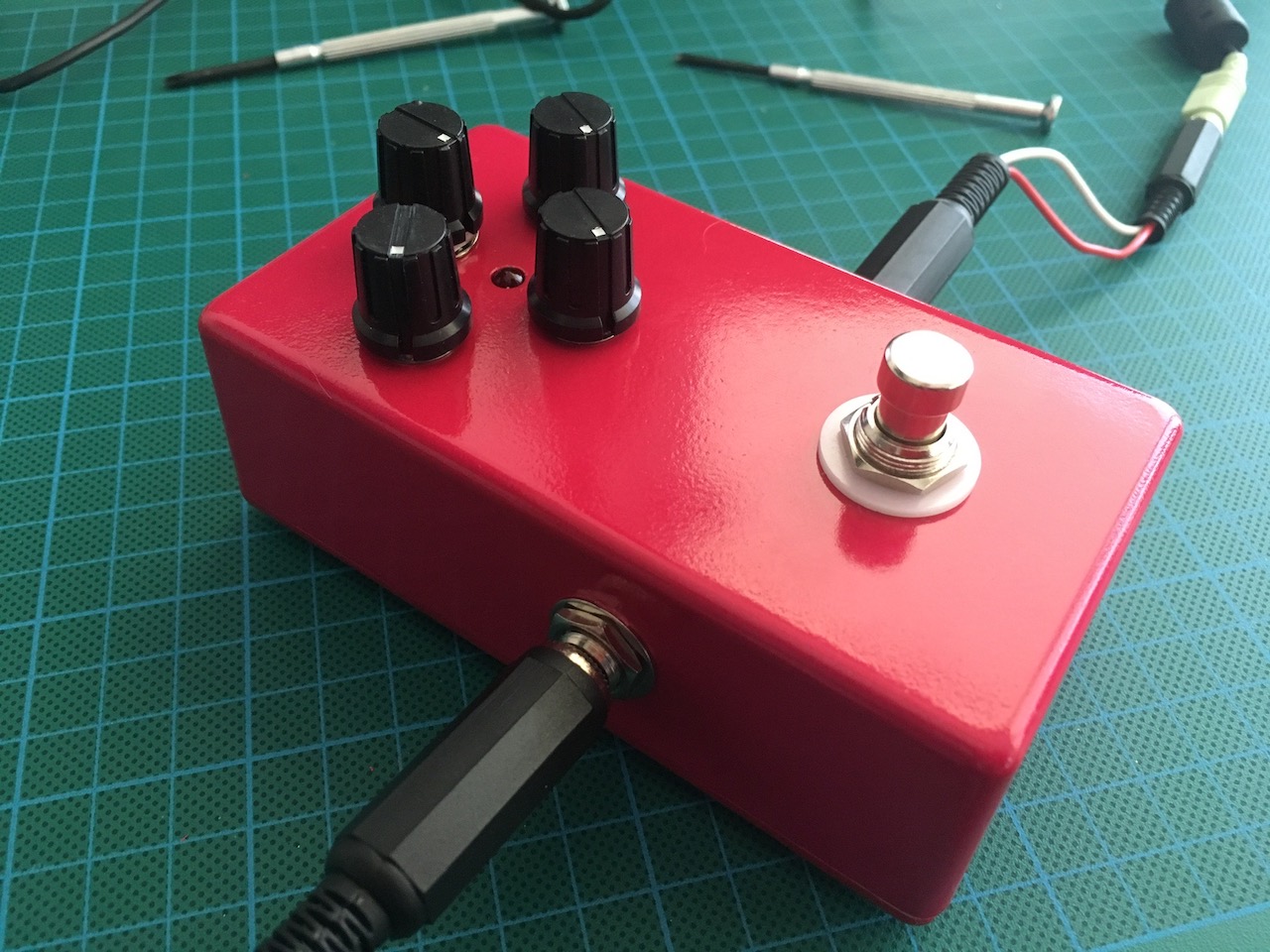
The pedal was then sealed and ready for testing.
Here's a video I put together of the assembly - it's hours of work sped up to just a few minutes.
Don't forget to check out Ilia Rogatchevski and his band Sebastian Melmoth.
If you're interested in how the pedal case was painted, that is written up here: Painting the BYOC Mouse Guitar Pedal case.
If you want to read about how this pedal was tested, head on over here: Testing the BYOC Mouse Guitar Pedal.
-i
