I've written a previous article that explains how to open this bulb to access its circuitry, have a read of that first before continuing.
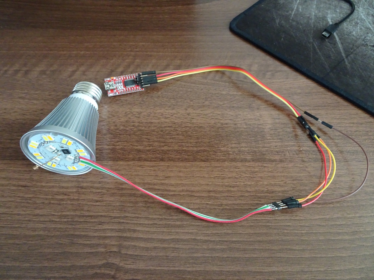
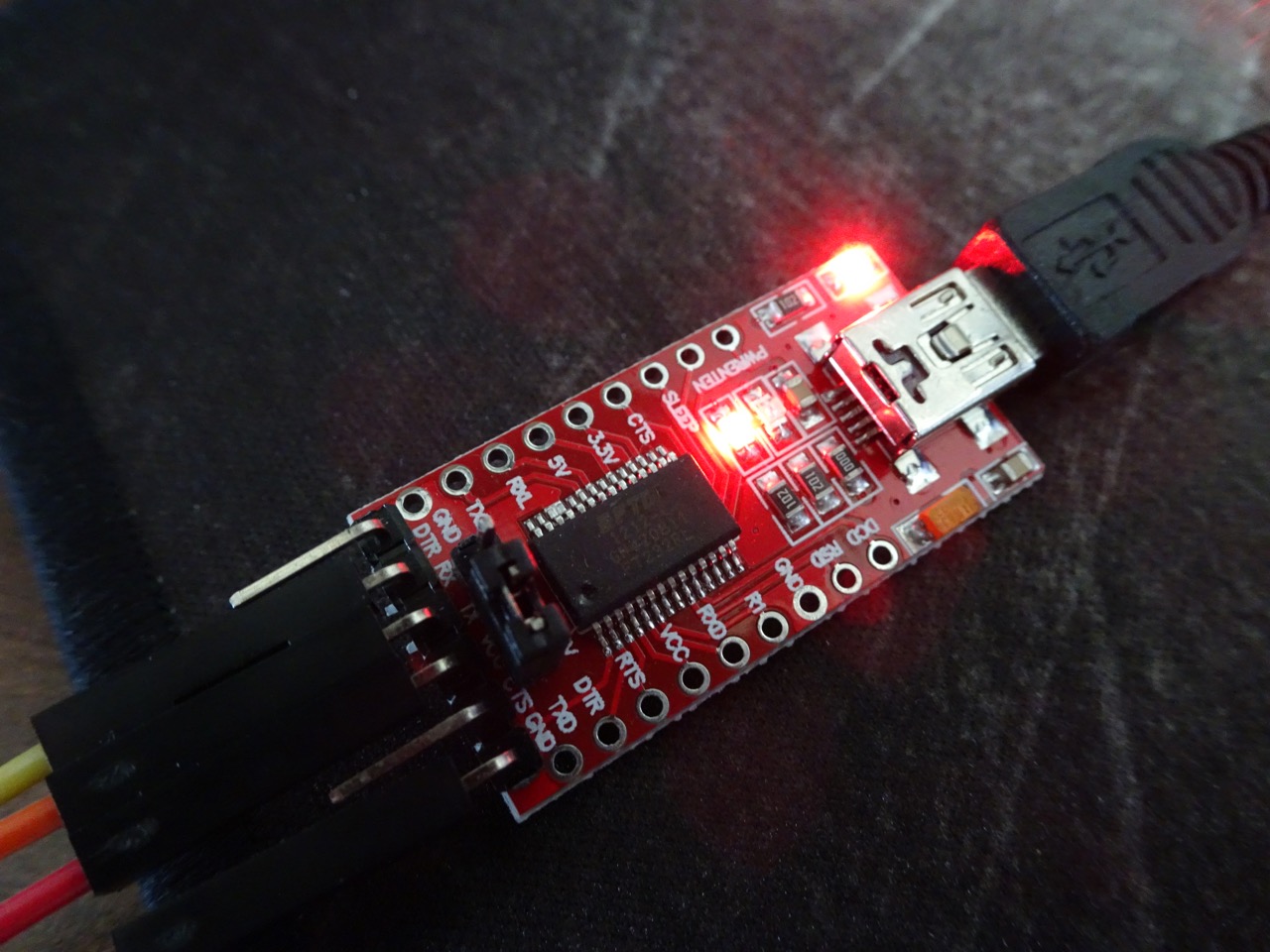
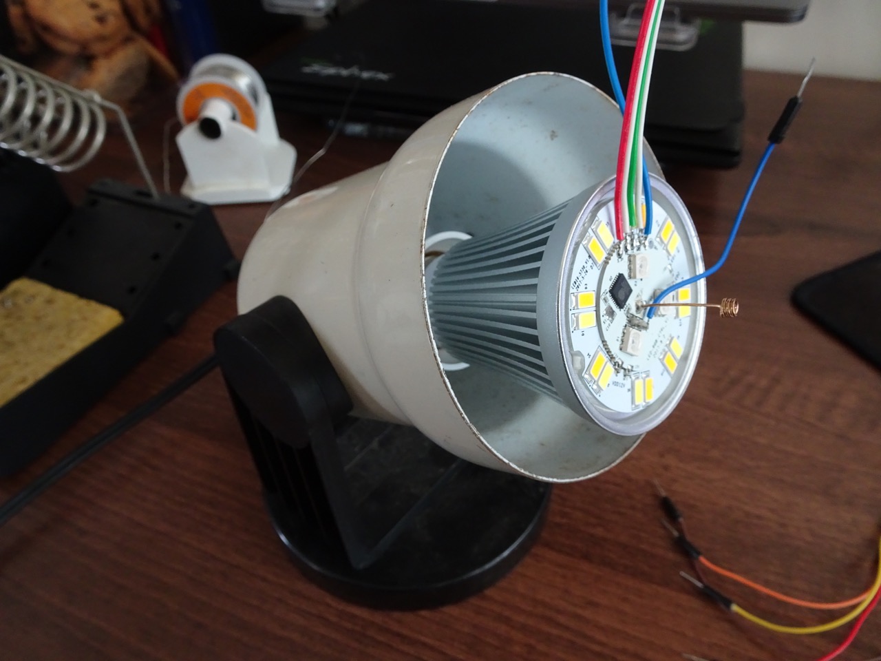
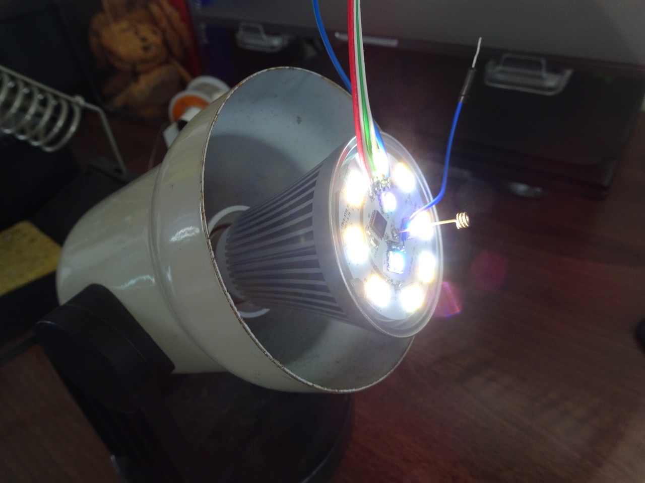
After everything was connected, the setup with an RS232 FTDI device looked something like this (minus the GPIO/GND wires for setting programming mode)...
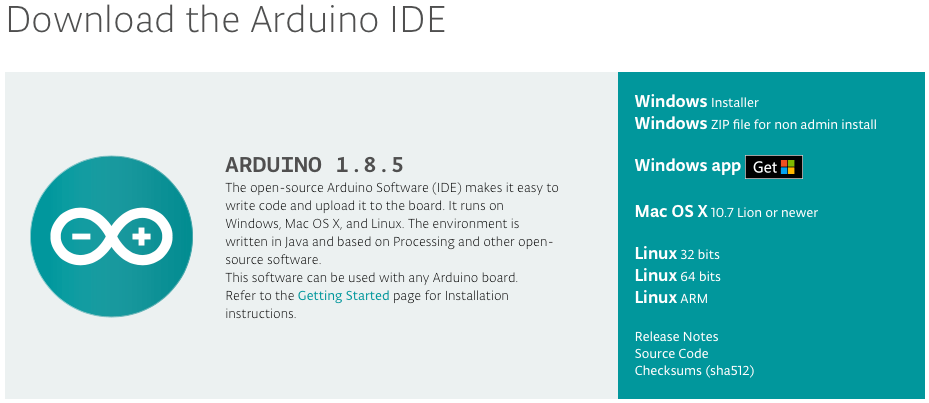
However the first step that needed to be done was to set up the software. I did all of this on a Mac so if you're following along and aren't using a Mac, some directories will be different. I installed the Arduino IDE 1.8.5 first.
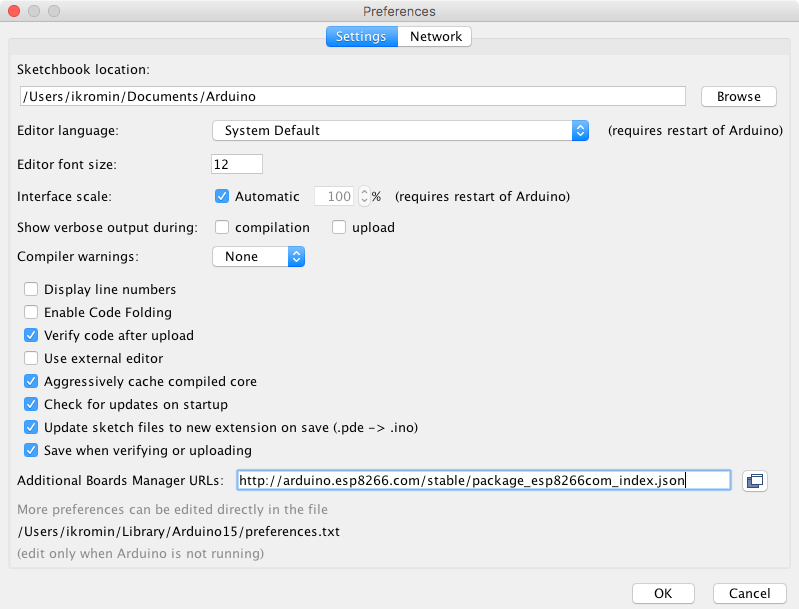
After installing the IDE, in its Preferences I added http://arduino.esp8266.com/stable/package_esp8266com_index.json to the Additional Board Manager URLs setting.
Then I clicked the Tools > Board > Board Manager... menu item.
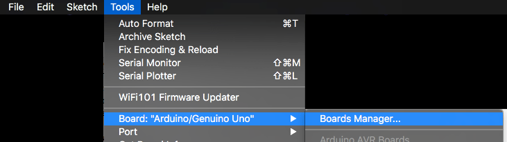
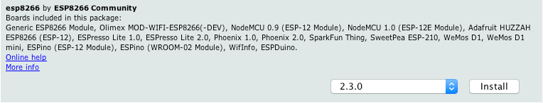
From the Board Manager, I found the esp8266 module and installed it.
After installing that module, I downloaded a clone of the arendst/Sonoff-Tasmota git repository and copied all of the directories from the Sonoff-Tasmota-development/lib directory to ~/Documents/Arduino (this location will be different if you're on Windows).

The IDE was more or less setup now but needed to be restarted first. After restarting I openined the Sonoff-Tasmota-development/sonoff/sonoff.ino file.
The Sonoff B1 bulb is an ESP8285 device, so that's what I selected from the Tools > Boards menu.

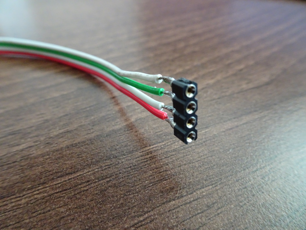
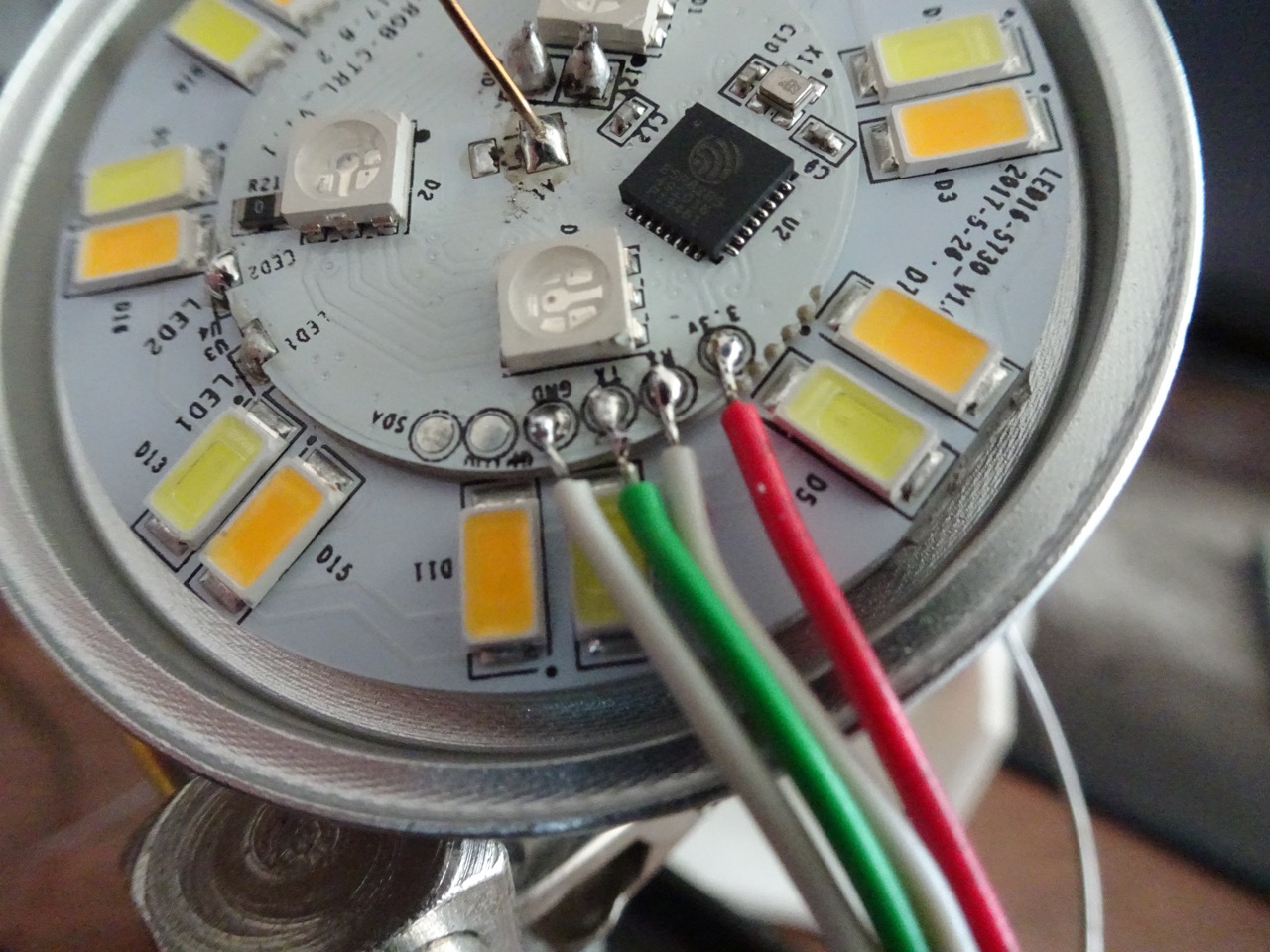
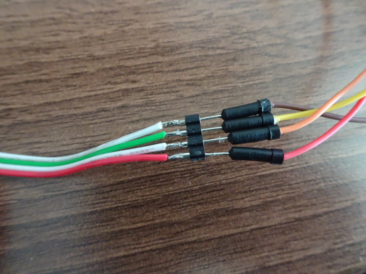
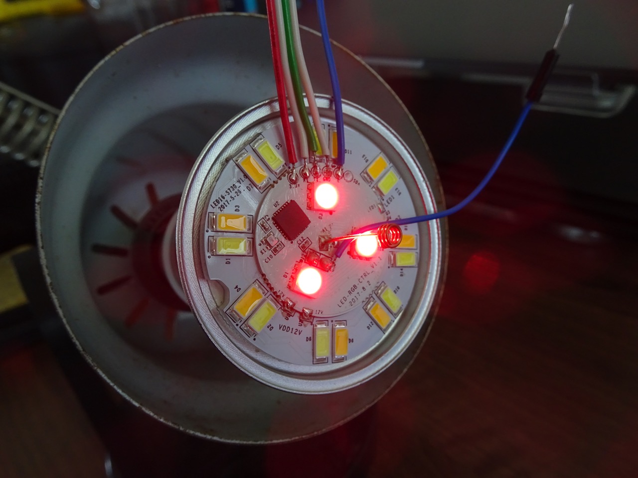
Next it was time to make some modifications to the B1 PCB. I soldered a header to some wires and then to the 3.3V, RX, TX and GND pads on the B1 PCB.
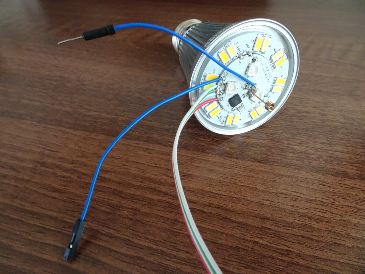
Then, I added an additional two connectors to the GPIO and the centre GND pads on the B1 PCB. These were used for setting the B1 into programming mode and I needed to be able to be connect/disconnect these. I used a male connector on one end and a female connector on the other.

Back to the Arduino IDE, I opened the user_config.h file and modified the following defines (change as required)...
user_config.h
#define WIFI_IP_ADDRESS "192.168.1.200"
#define WIFI_GATEWAY "192.168.1.1"
#define WIFI_SUBNETMASK "255.255.255.0"
#define WIFI_DNS "192.168.1.2"
#define STA_SSID1 "MyWiFiNetwork"
#define STA_PASS1 "wifi_password"
#define MQTT_USE 0
With my WiFi and IP settings in place it was time to connect everything and upload the new firmware. The RX pin on the FTDI was connected to the TX pin on the B1 and TX on FTDI to RX on the B1. The GND pins were connected together and the 3.3v B1 pin was connected to VCC on the FTDI. The FTDI was set to 3.3v of course.
Before connecting the FTDI to the computer, the blue wires (GPIO and GND) on the B1 were connected together. Then, after connecting the FTDI to the computer and waiting a few seconds, the blue wires on the B1 were disconnected. This put the B1 into programming mode as mentioned earlier.
In the Arduine IDE Tools menu, I had to make a couple of extra changes. The Flash Size was changed to 1M (64K SPIFFS). The Port was set to /dev/cu.usbserioal-00000000 (this could be different depending on your FTDI and OS).
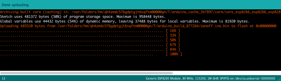
Finally it was time to upload the firmware! This was done by clicking Sketch > Upload. A couple of minutes later the firmware was compiled and uploaded to the B1.
I disconnected the FTDI from my computer, disconnected the B1 from the FTDI and plugged the B1 into my mains light bulb socket and then switched it on.
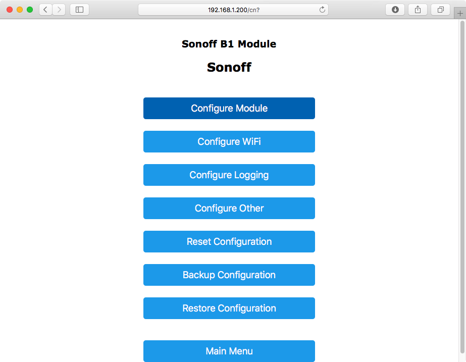
The web UI was available pretty much immediately from the IP address I set up in user_config.h, in my case it was http://192.168.1.200/. First thing to do here was to tell the Tasmota firmware that it was controlling the B1 module. That was done from Configuration > Configure Module.
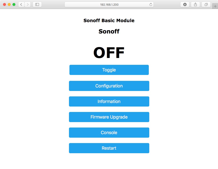
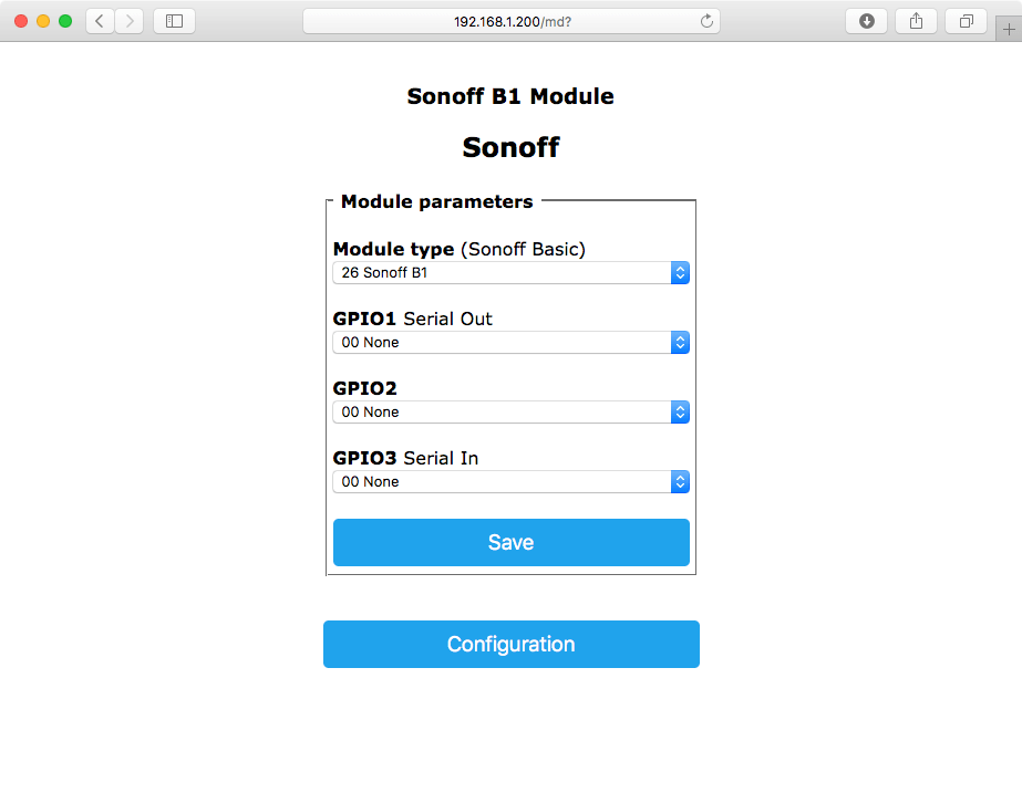
I set the module type to 26 Sonoff B1 and saved. After getting back to the main screen I could toggle the B1 on/off. Success! I went over to the Console and played around with some colour setting commands, it was working as expected too.
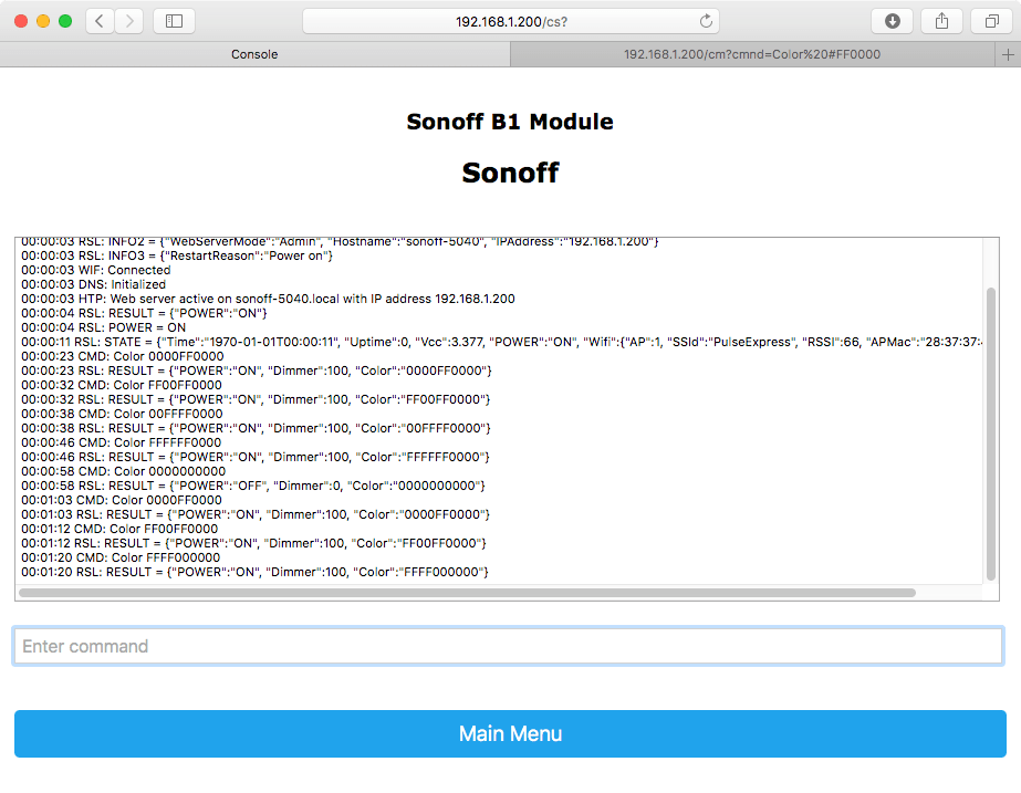
I was able to change the colour of the RGB LEDs as well as control the blue/warm settings for the while LEDs.
That's it for this part of the project. I'm going to put together a Java app to allow me to control the B1 further and in a way that responds to the colours on my screen. Should be cool once it's done. Stay tuned!
-i
