The instructions I followed didn't cover all of the steps, didn't have many in-progress photos and left out some very important steps around removing the polarising foil from the NGP screen. This is a guide that covers how to add a back light (available from Hand-Held Legend) to a Neo Geo Pocket.
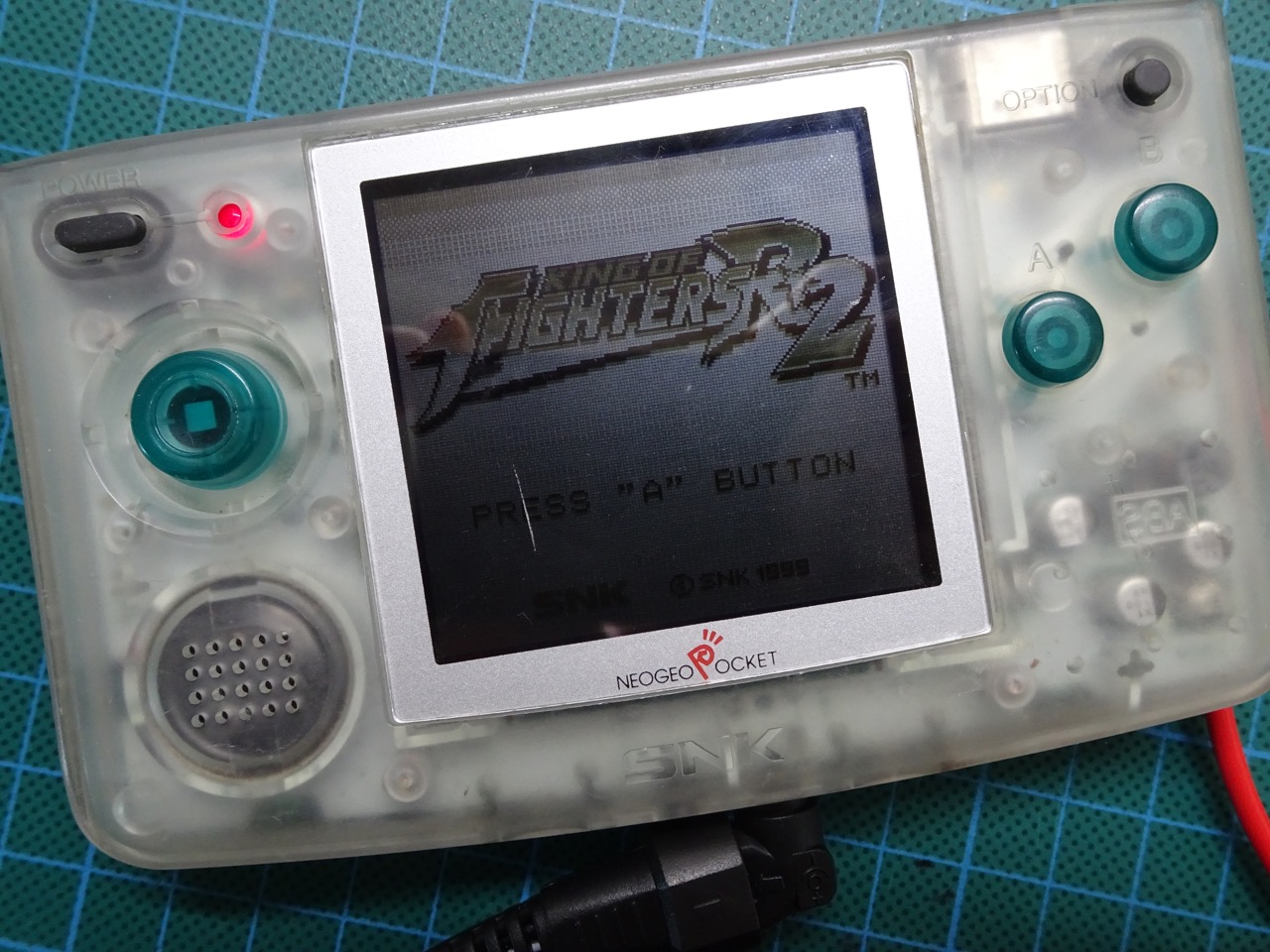
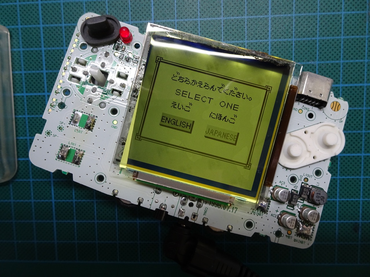
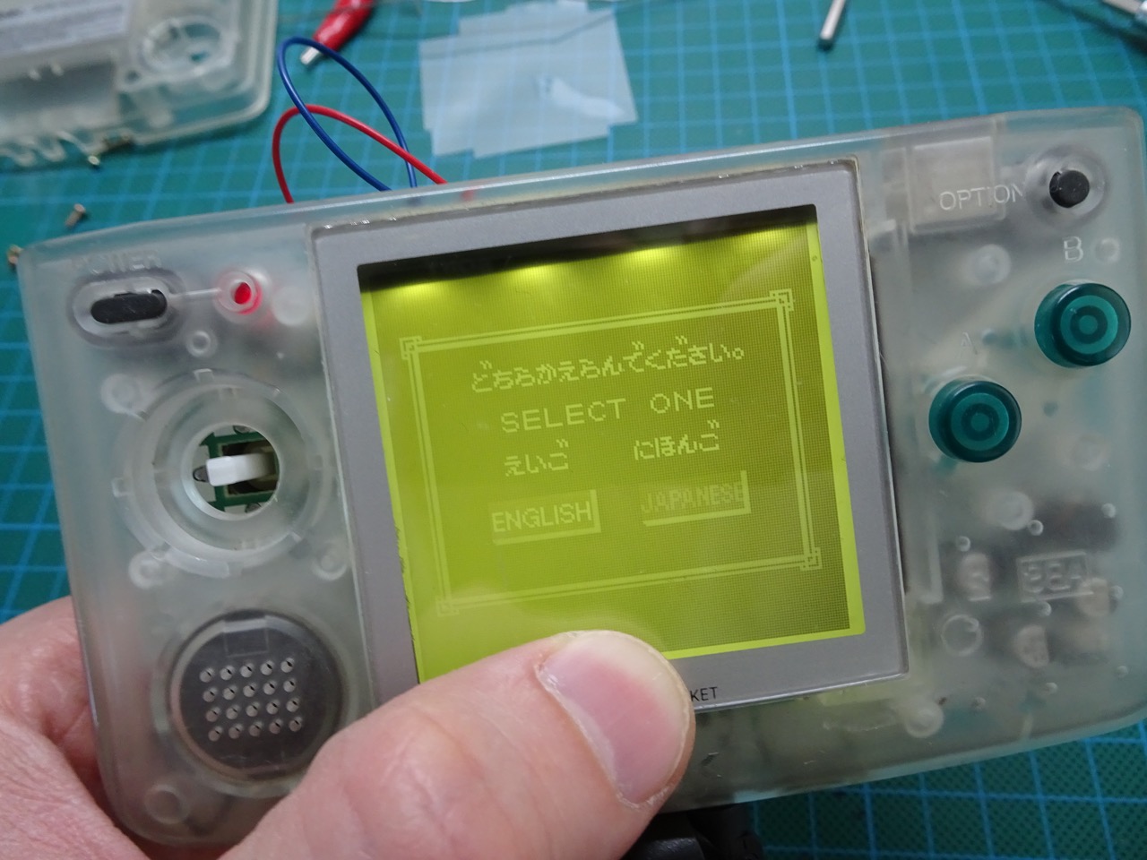
For reference, this is what a standard NGP screen looks like. This is my NGP prior to the mod.
Tools and parts you will need
- Phillips Screwdriver
- Flat head Screwdriver
- Tri-wing Screwdriver
- Scalpel/Exacto Knife
- Needle nose pliers
- Soldering Iron and solder
- Game Boy Backlight (DMG or Color)
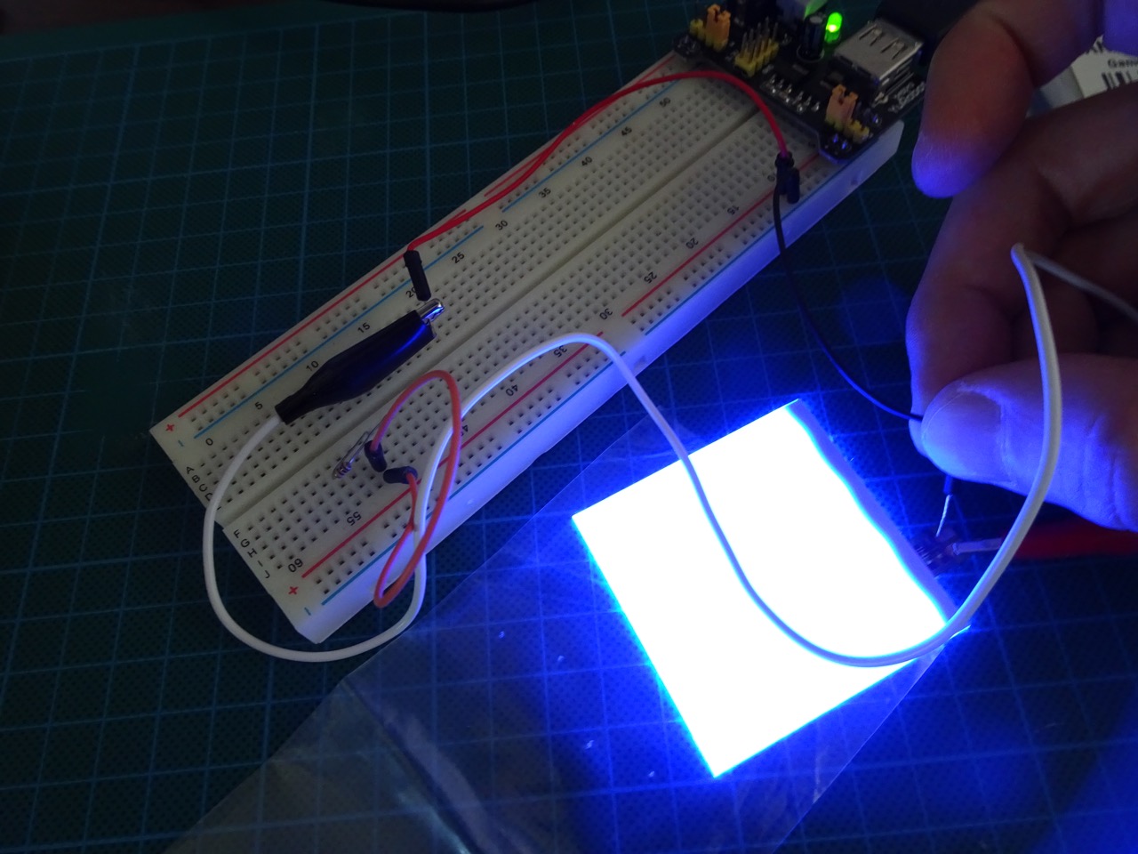
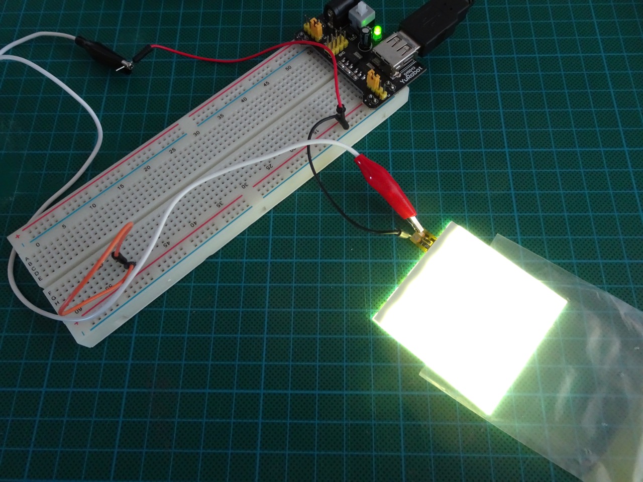
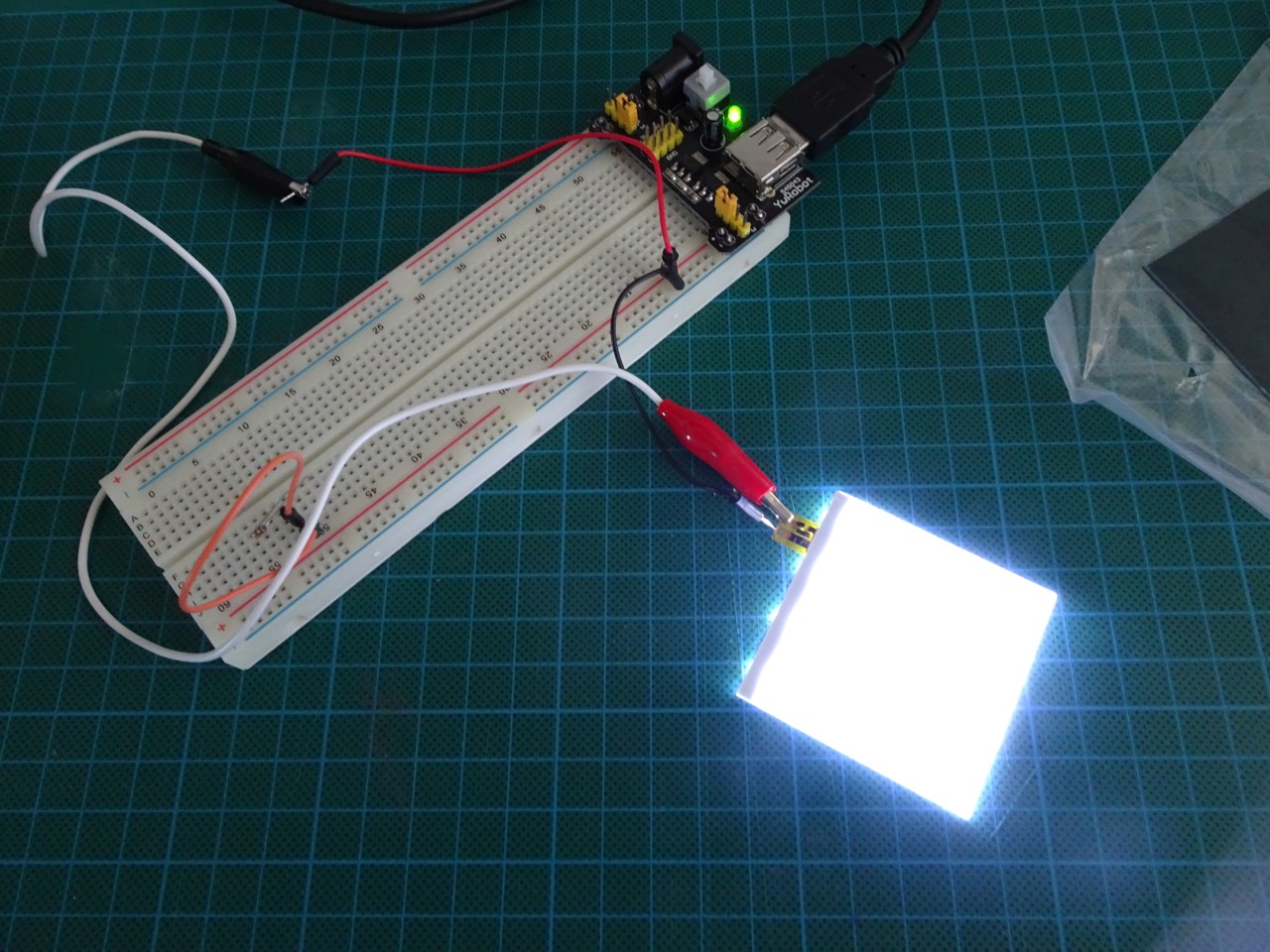
A quick note: I ordered three colours for the back light - White, Blue, Washed Yellow. After testing out each one I decided that Washed Yellow was the colour I liked the best. To test these I simply hooked them up to a 5VDC power source.
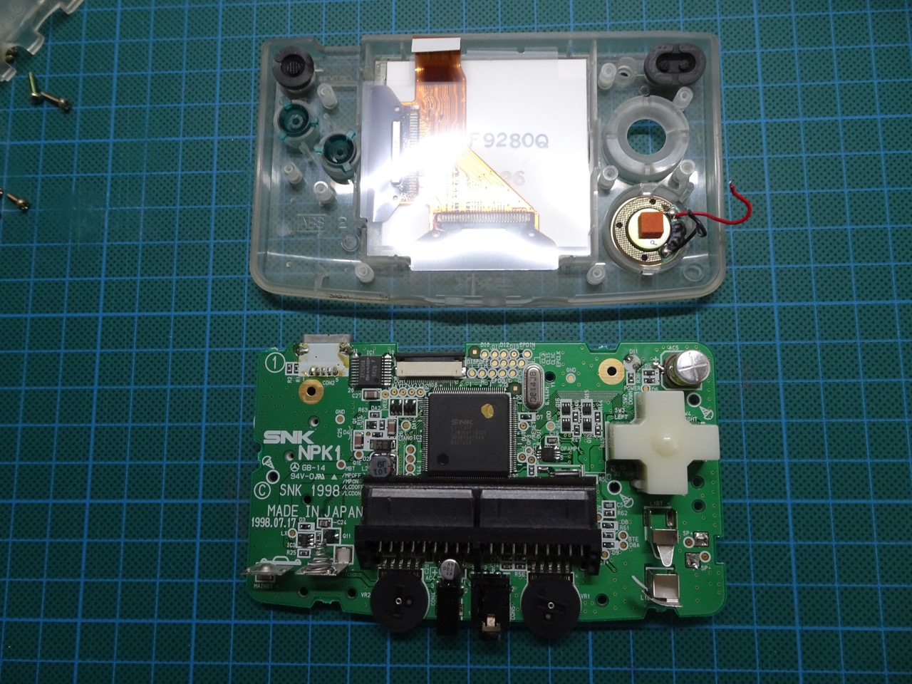
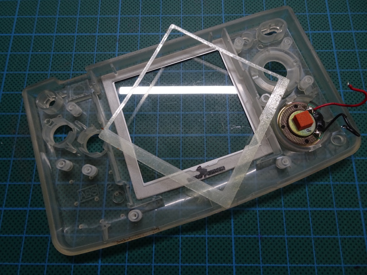
Opening and Disassembling the Neo Geo Pocket
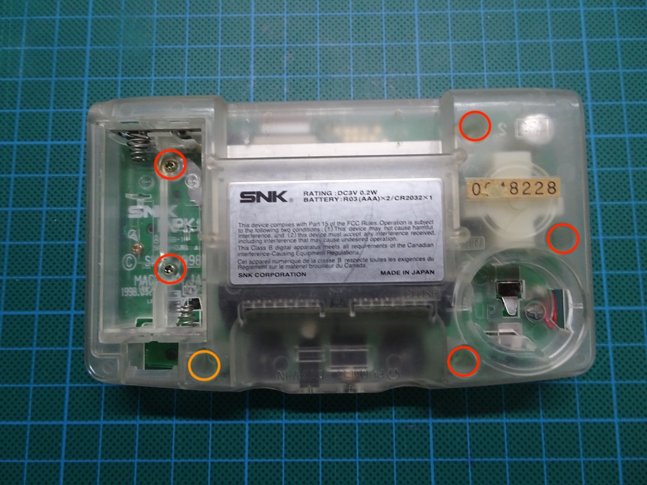
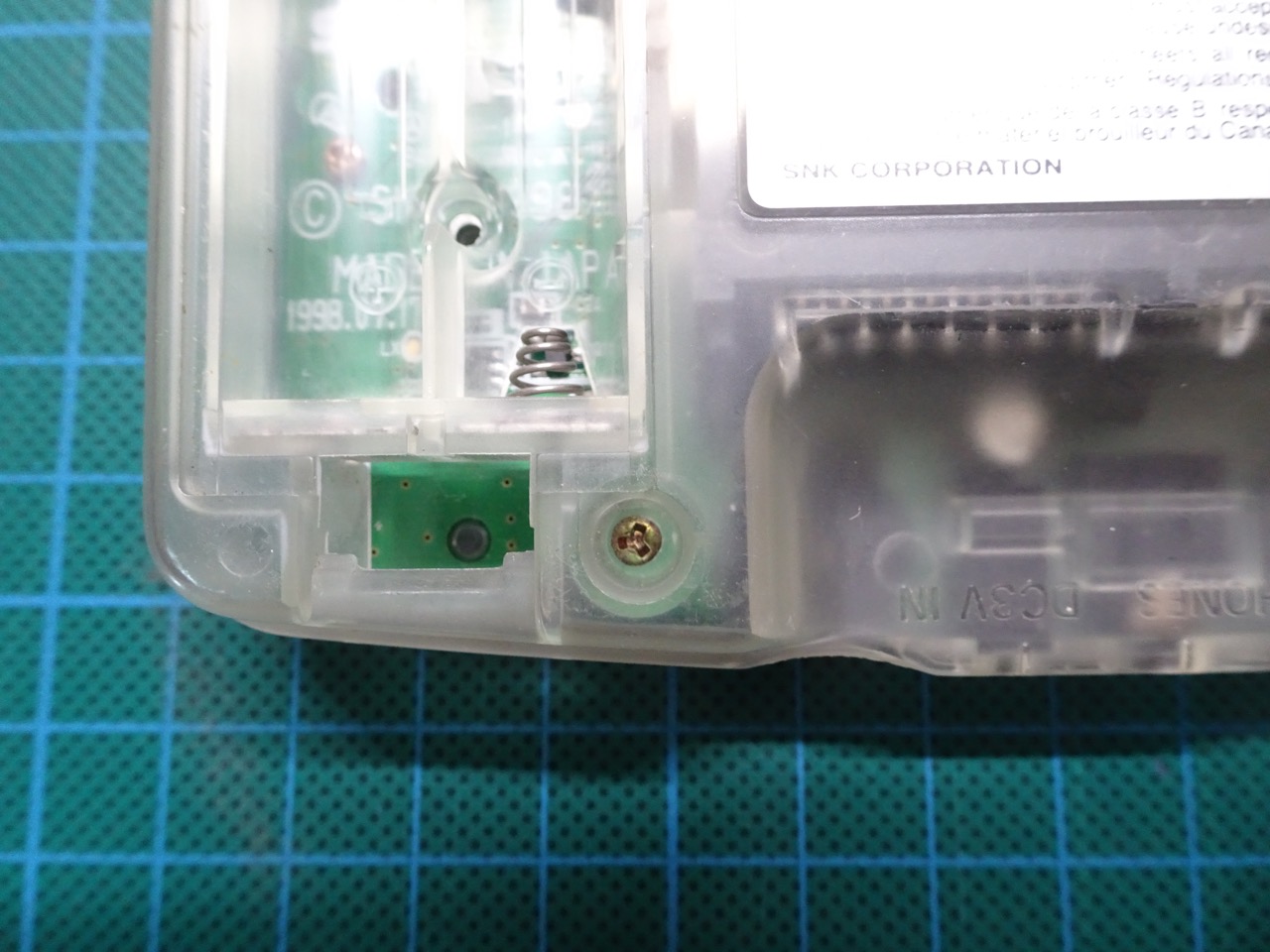
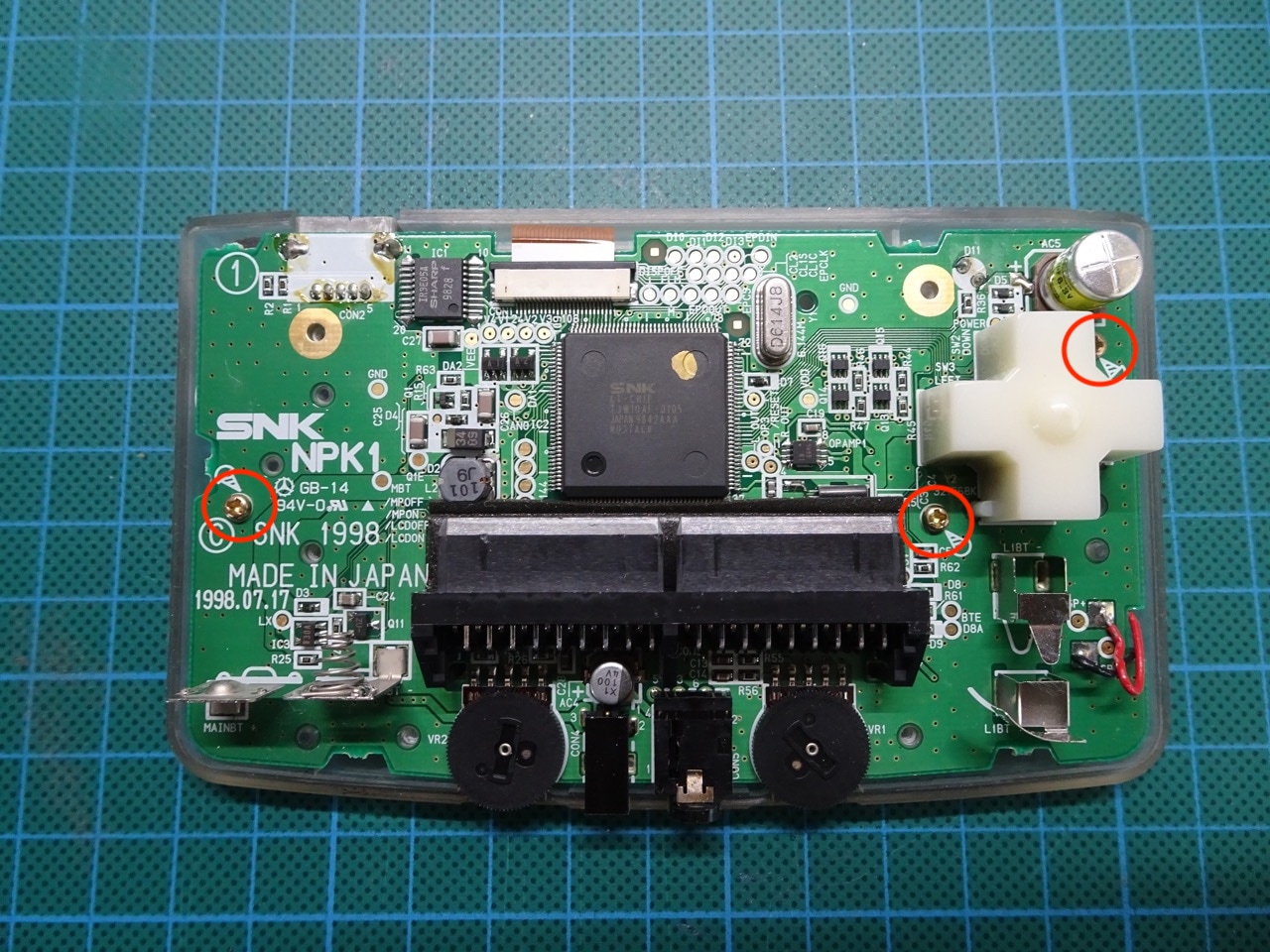
This step requires a tri-wing and a Phillips screwdriver. There are 5 Phillips screws (red) and 1 Tri-Wing screw (orange). After unscrewing the screws the case should come apart into two parts.
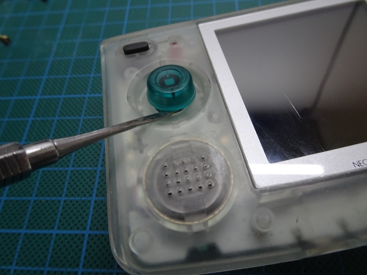
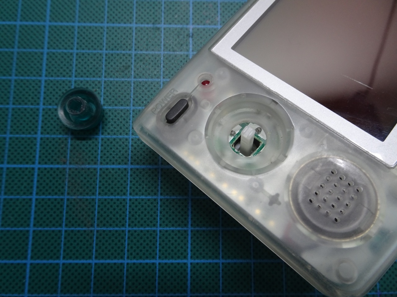
Take the half with the screen and turn it the right way up to remove the joystick. Using either a flat head screwdriver or something else flat, slide it under the joystick cover and push straight up, it will slide off with not too much pressure.
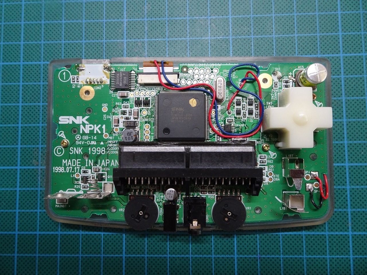
Now the motherboard can be removed. There are three Phillips screws holding it in place.
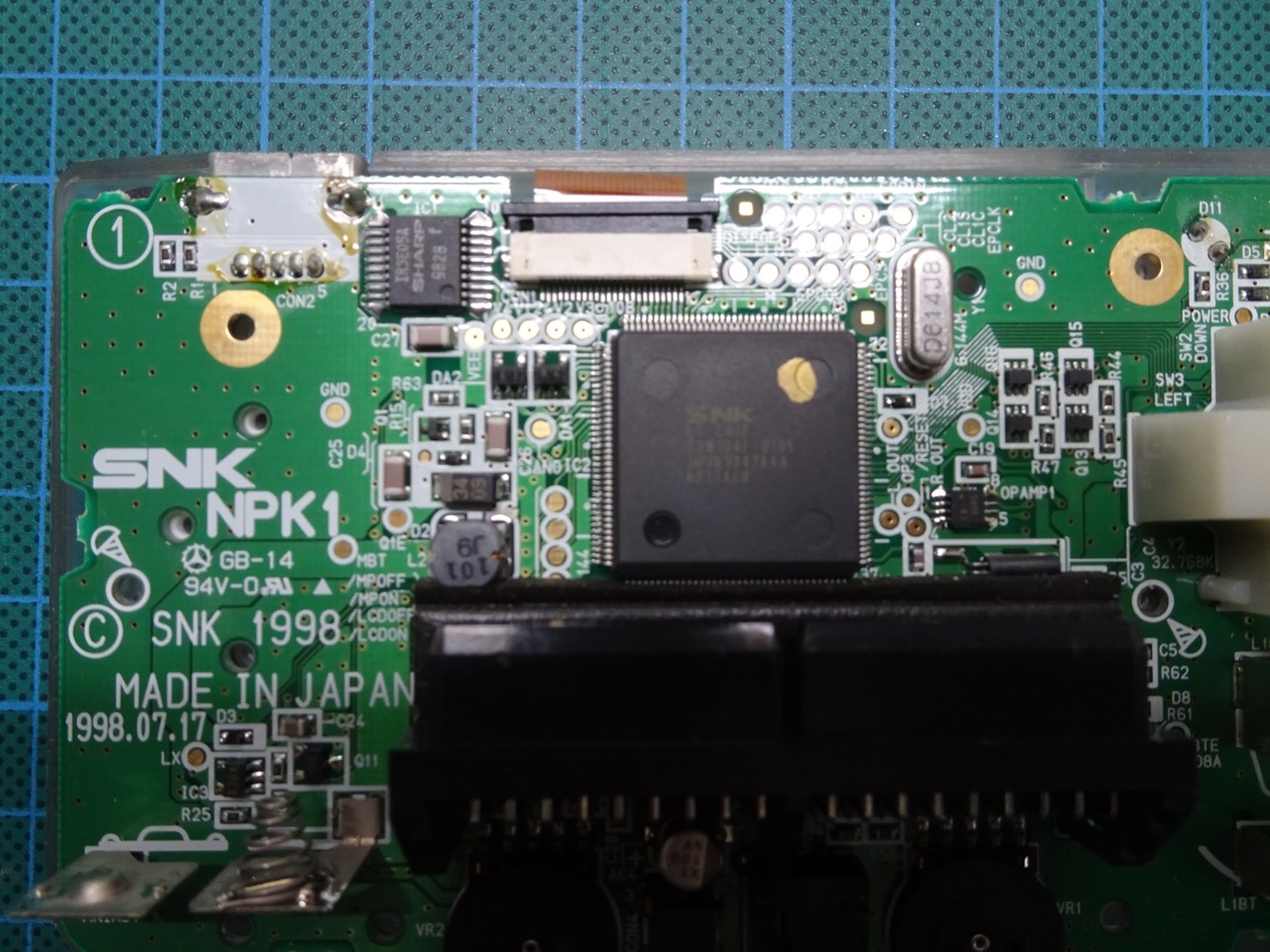
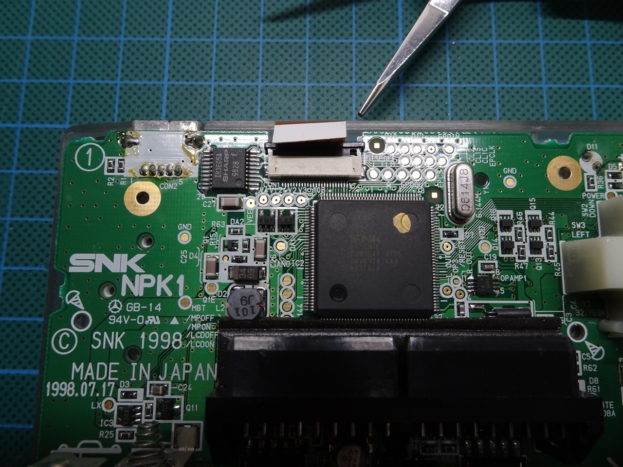
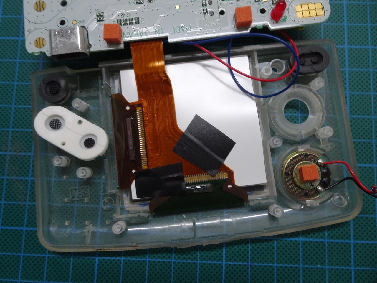
The screen ribbon cable can be disconnected next. There is a ZIF socket holding it in place. The socket has a sliding top section that needs to be pushed up to release it from clamping down the ribbon. Once that's done the ribbon cable can be easily pulled out of the socket.
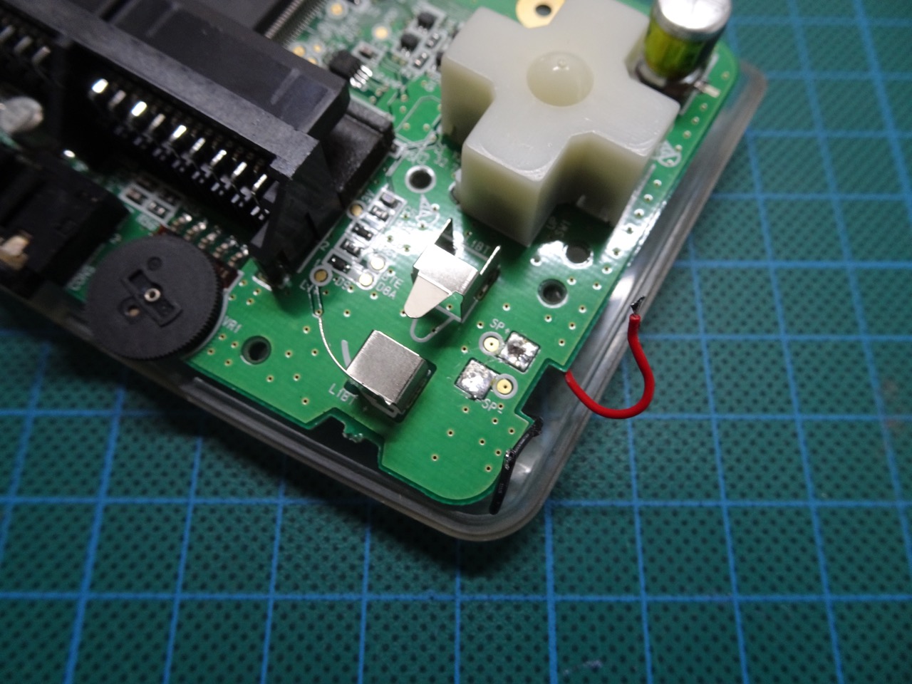
The speaker wires need to be desoldered next.

At this point the motherboard and the screen can be separated - there's nothing holding the motherboard in place any more.
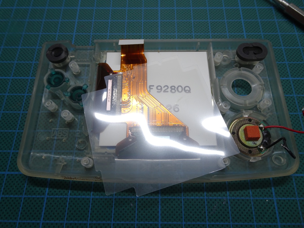
Removing the LCD
The LCD screen is glued into place with quite strong adhesive. You need to take extra care in these next few moments as it is possible to crack the LCD if you apply too much pressure. It's best to use a wide flathead screwdriver for this.
First remove the protector plastic sheet.
Using a flathead screwdriver, wedge it under the bottom of the LCD and gently push up. The LCD should start separating from the adhesive that is holding it down. Gently lift the LCD, the adhesive will unstick as you do this.
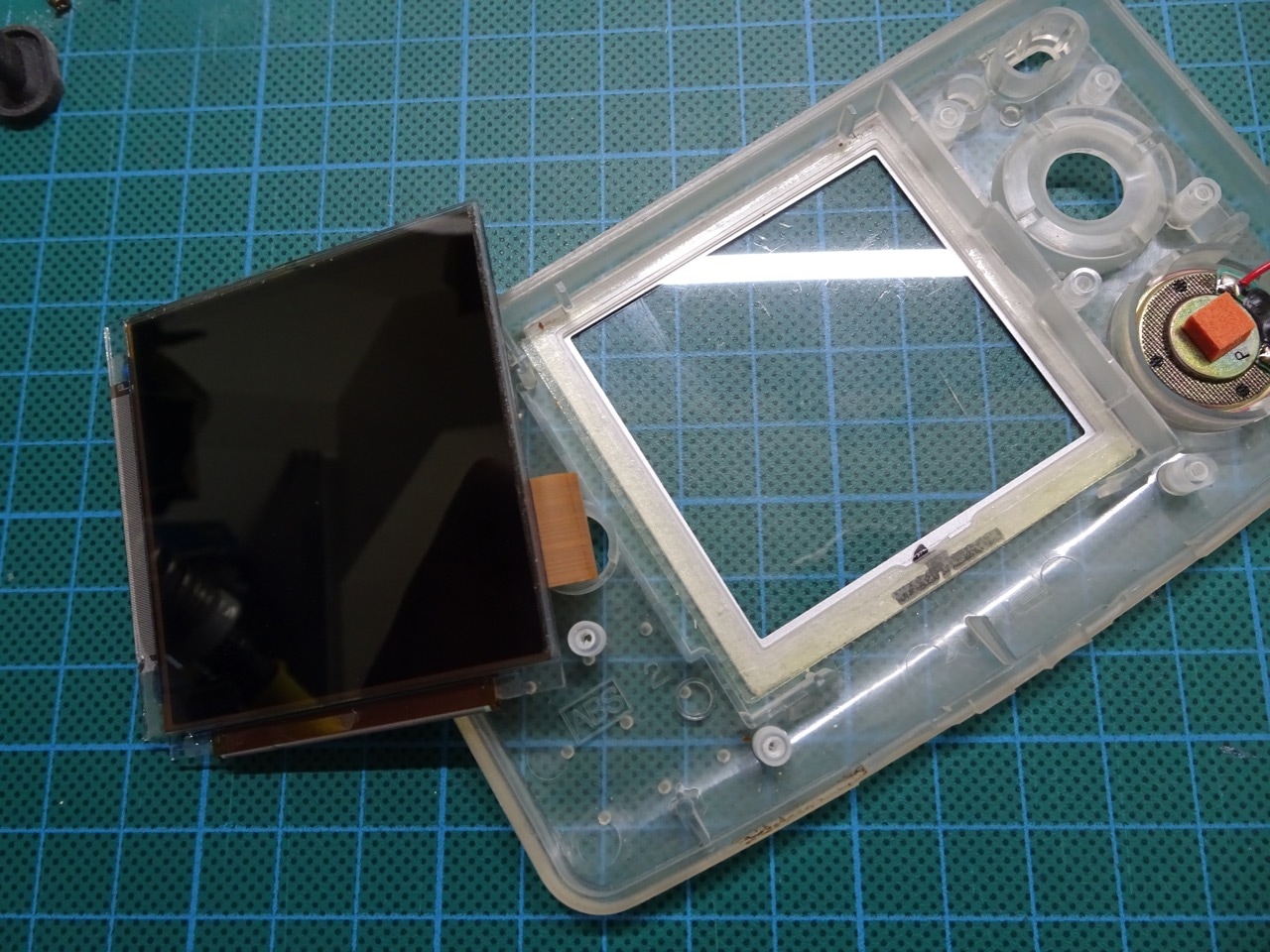
Remove the adhesive surround that was holding the LCD in place, it won't be needed.
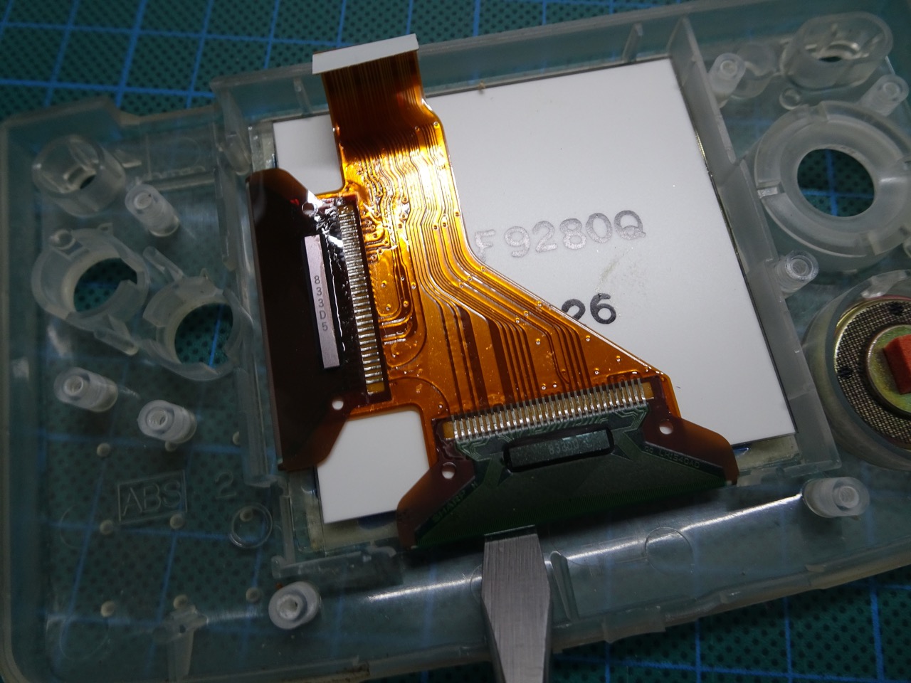
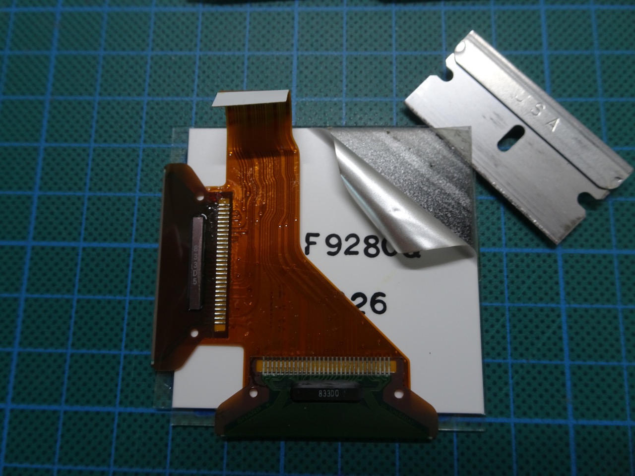
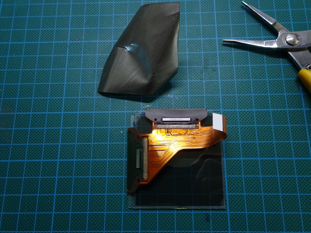
Removing the Polarising Foil from the LCD
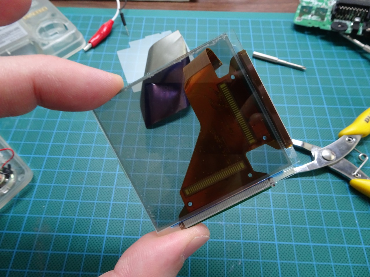
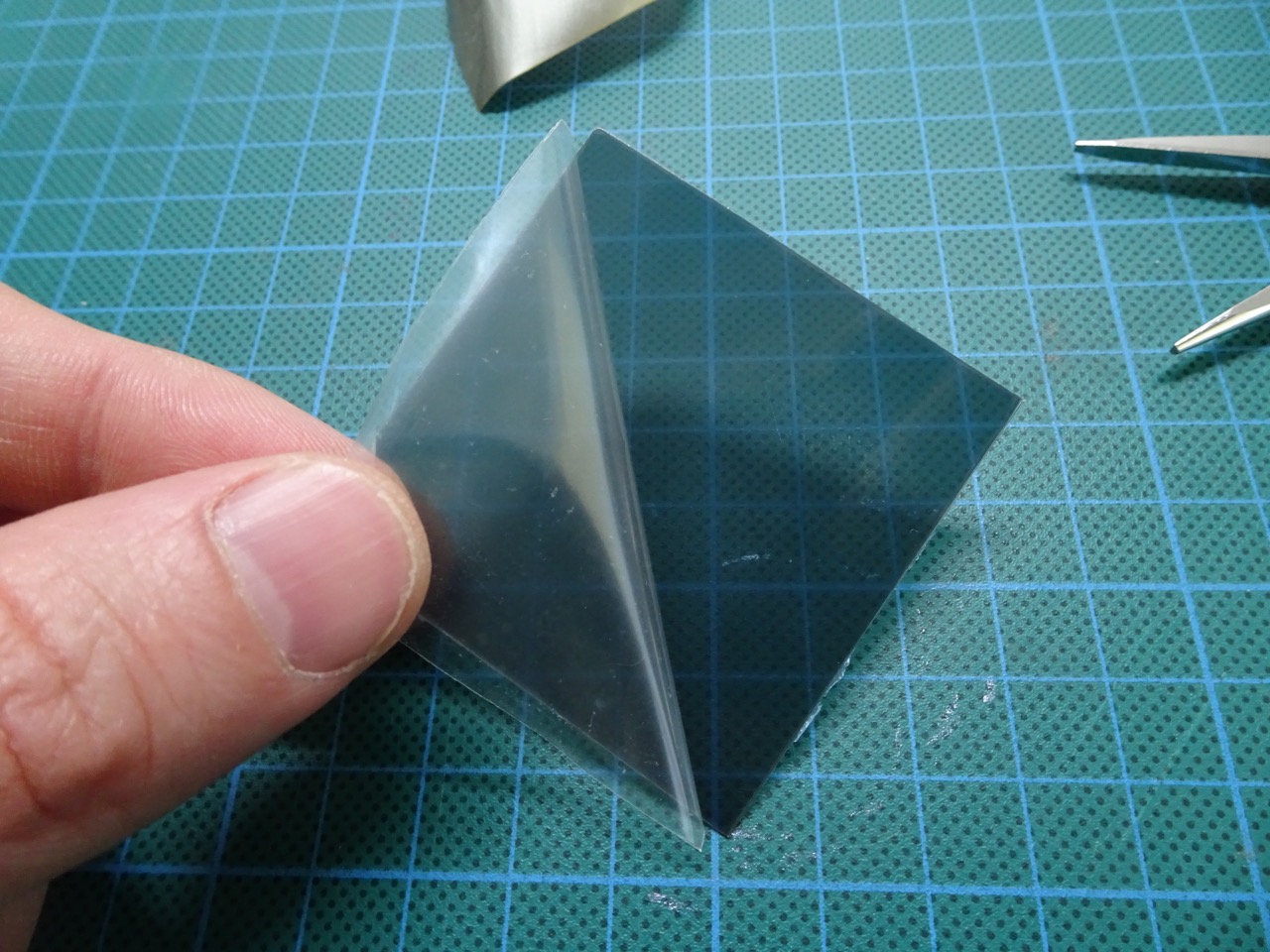
With the LCD free, the next step is to remove the polarising foil from the back. This foil seems to have two layers and the first time I started to do this I only got the rear layer. If you see a layer of glue being left behind then go back and slice the second layer off, it should feel like fairly rigid plastic. Where the foil is removed, the LCD should be completely see-through. Any remaining glue can be removed with a blade.
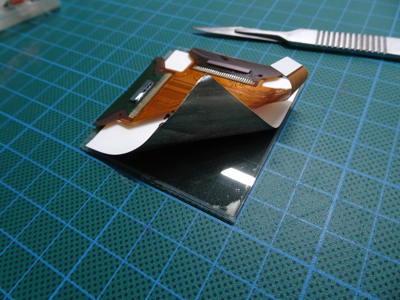
The positioning of the ribbon cables around the LCD makes it difficult to remove the foil. I ended up lifting it in the corner between the two ribbon cables as well. Once I removed a portion of it, it was possible to bend it under the ribbon cables and use needle-nose pliers to pull it out the rest of the way. Be careful here and take your time, don't apply too much pressure on the foil or you will crack the LCD.
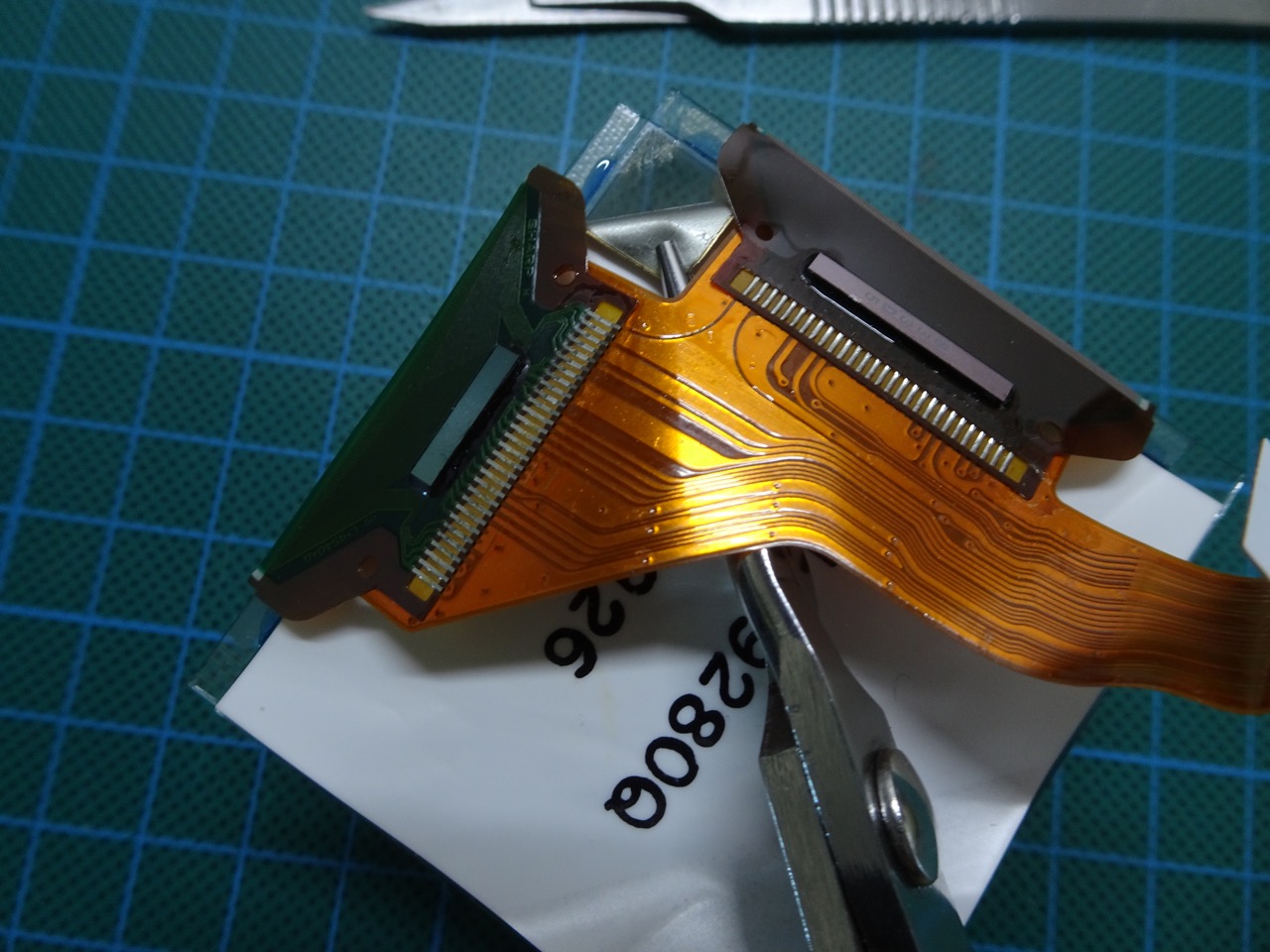
Once the foil is removed the LCD should look like this...
Test Fitting and Wiring up the Back Light
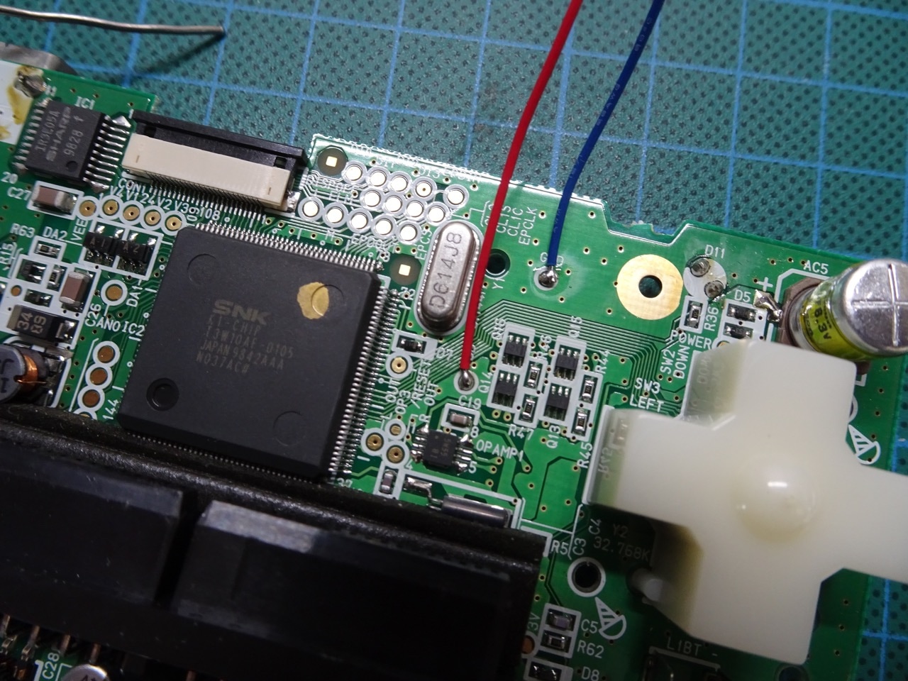
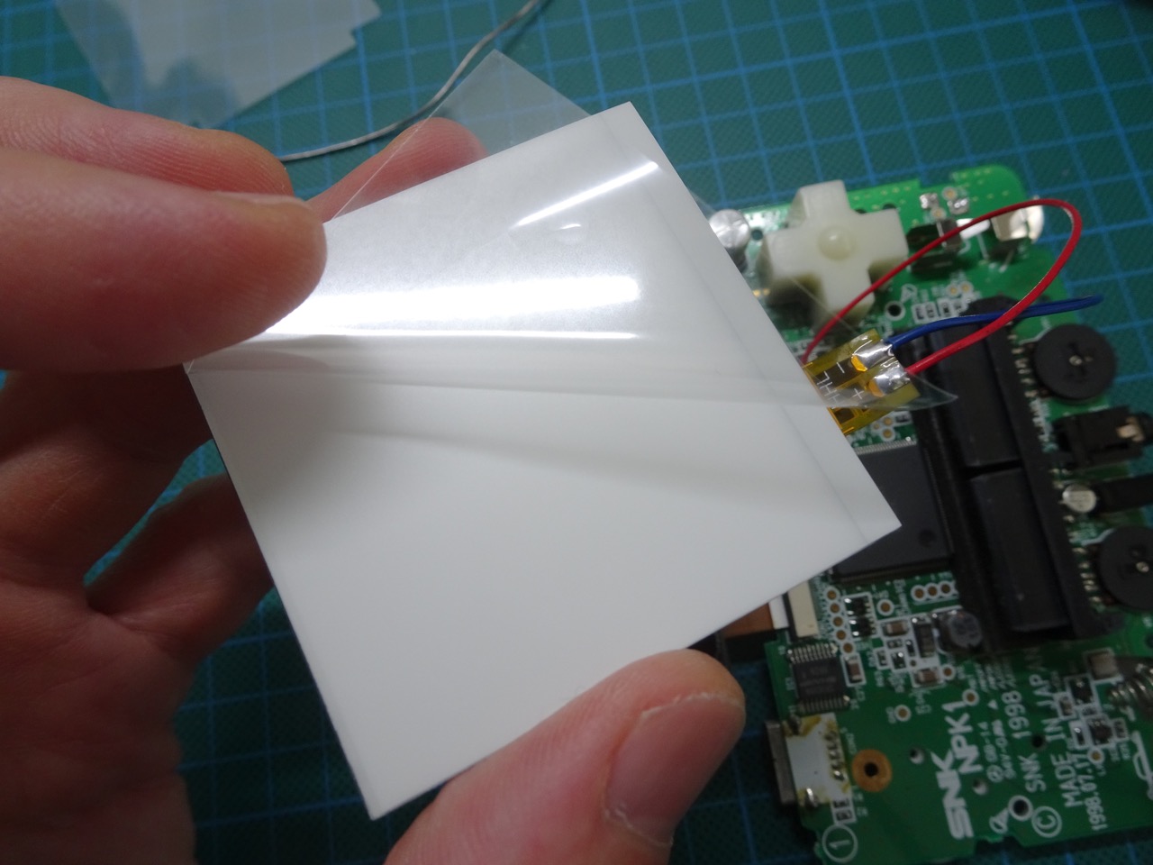
You can now take the polarising film that came with the backlight and sandwich it between the LCD and the backlight. At this point there is no need to remove any protective films as it's just a test fitting. At the same time solder the two wires to the back light ribbon cable connector and to the NGP motherboard as shown in the photos.
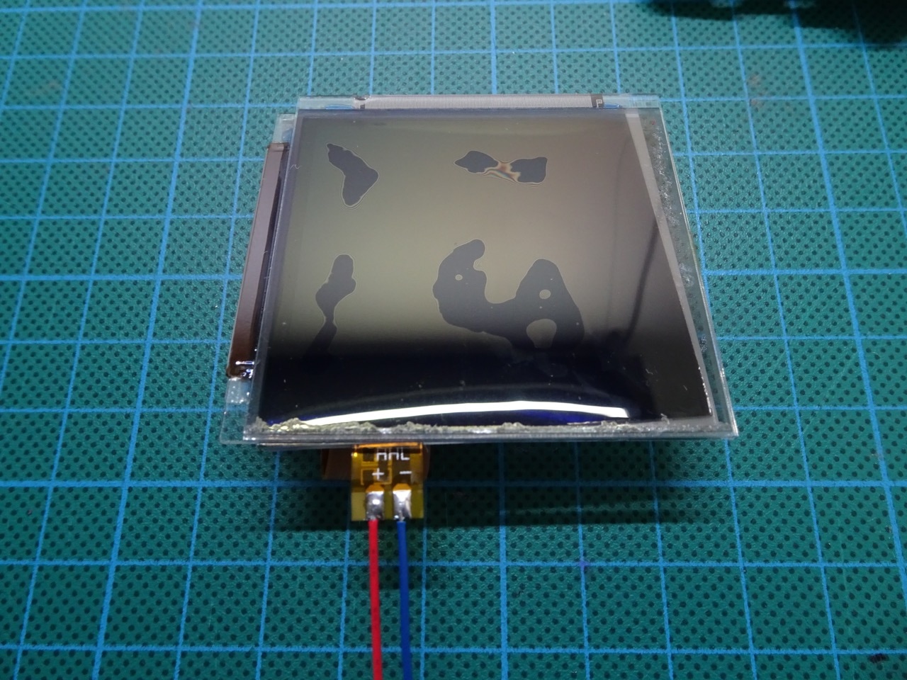
Reconnect the screen and turn on the NGP. The back light should be working. It will already look great! You may want to flip the polarising film around to get better contrast, or leave it as is, this is really up to experimentation.
Final Fitting and Adjustments
Both the back light and the polarising film have protective plastic on them, this needs to be removed.
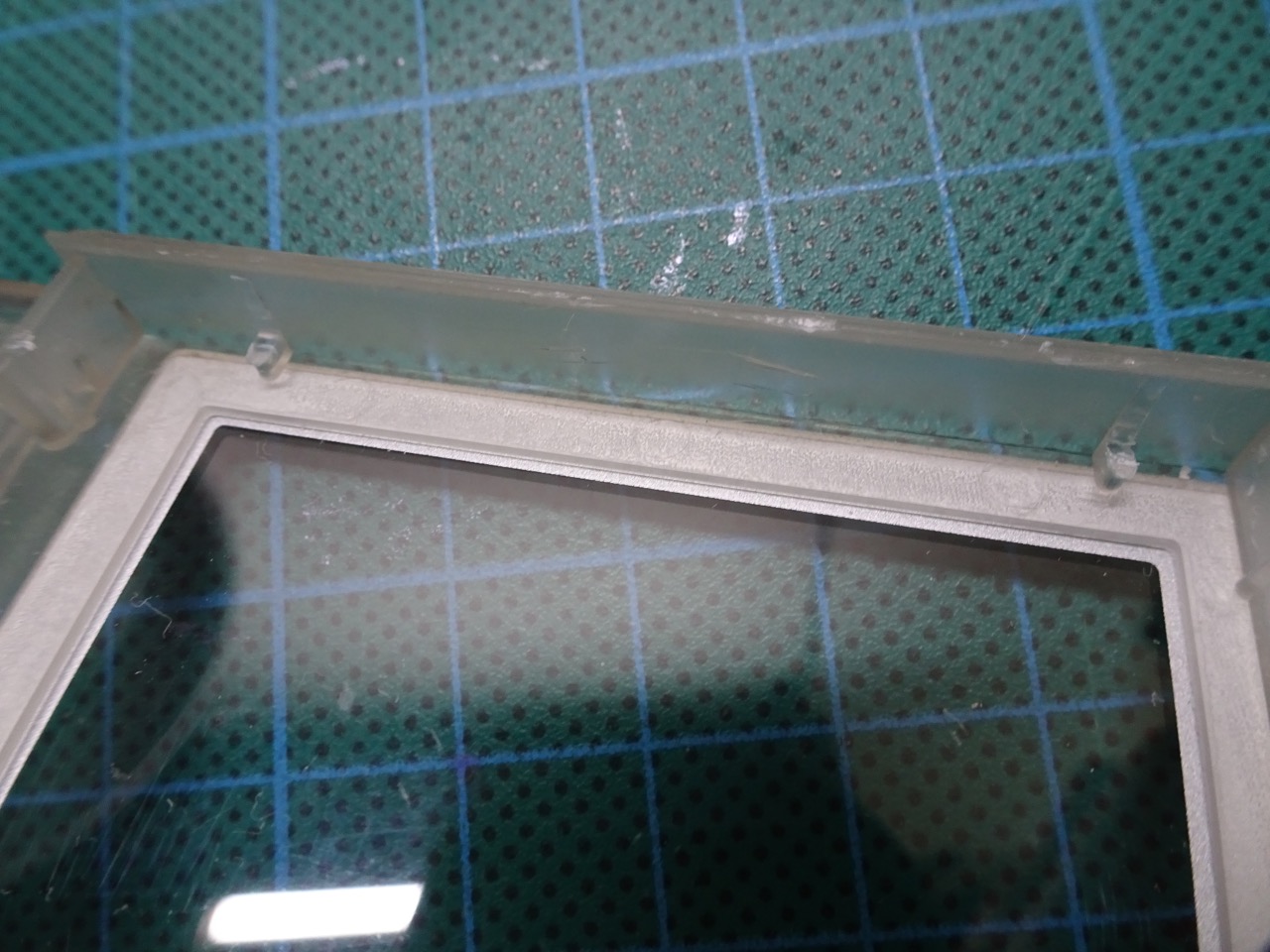
The case needs to have small notches cut away to make the front light sit correctly. There are posts on the top part of the screen area that hold the LCD in place. These are the posts that need to be cut away, however it is important to keep the bottom 1mm or so as is so that the LCD can be propped up against them. This can be done with a scalpel - this plastic cuts very easily, just be careful not to slip and cut the screen protector.
Then, re-insert the polarising film and back light and reconnect the screen (if you disconnected it since the previous step) and fit it into the case. It will take a few attempts to make it sit correctly. The back light needs to slide up and over right to the edge of the case - failing to do this will leave an ugly unlit/dark streak across the top of the LCD. Once I had the final correct positioning, I used electrical tape to hold the back light in place.
It actually took a few more attempts to get positioning right and then I noticed that there was dust between the LCD and the screen cover so I had to remove it all and clean everything, which resulted in more adjustments having to be made.
Eventually everything was aligned and cleaned up, the motherboard screwed back in place and the back of the case ready to be put back on. The speaker wires were also soldered back in place.
The end result was great (though I didn't quite get the alignment correct - noticed this too late).
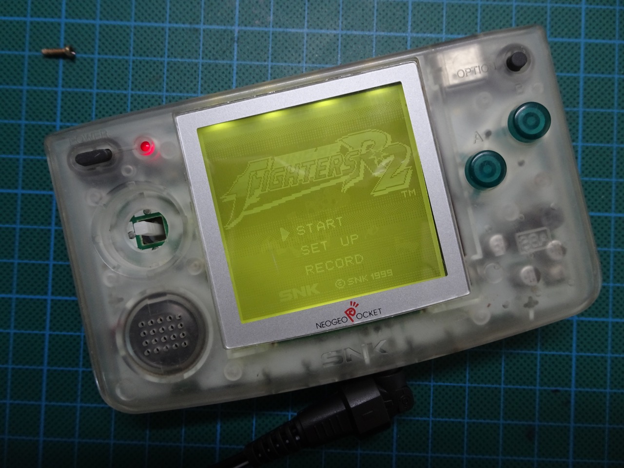
This mod is definitely worth doing and doesn't cost much. It takes around 1-2 hours to do. The NGP becomes so much better to play with a backlight!
-i
