There was no real purpose to this project apart from seeing whether these two separate headphones could function as one. I was originally intending to re-house them into a custom built case but never got around to it. I did however got the concept working.
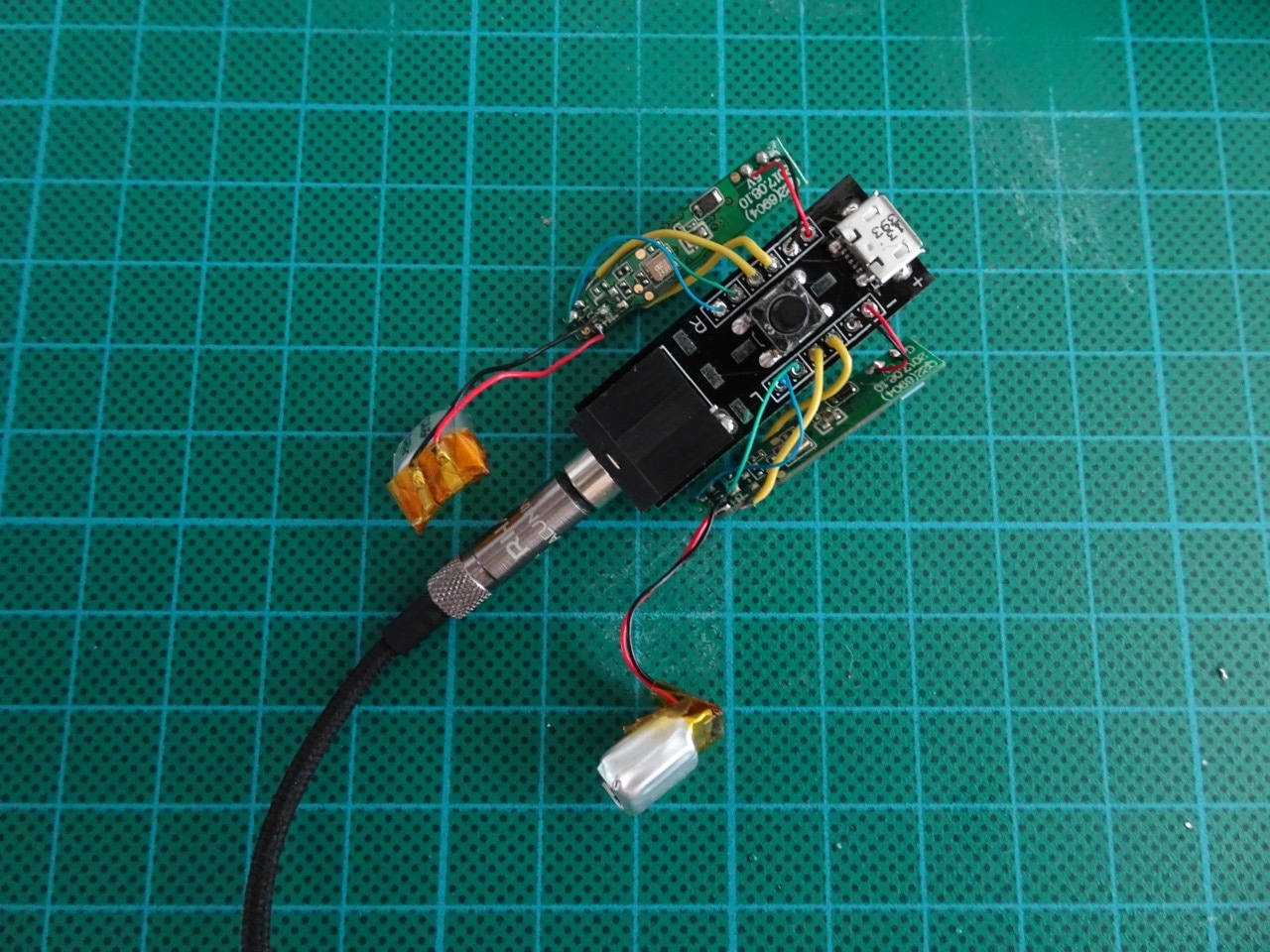
The end result was this Frankenstein's monster...
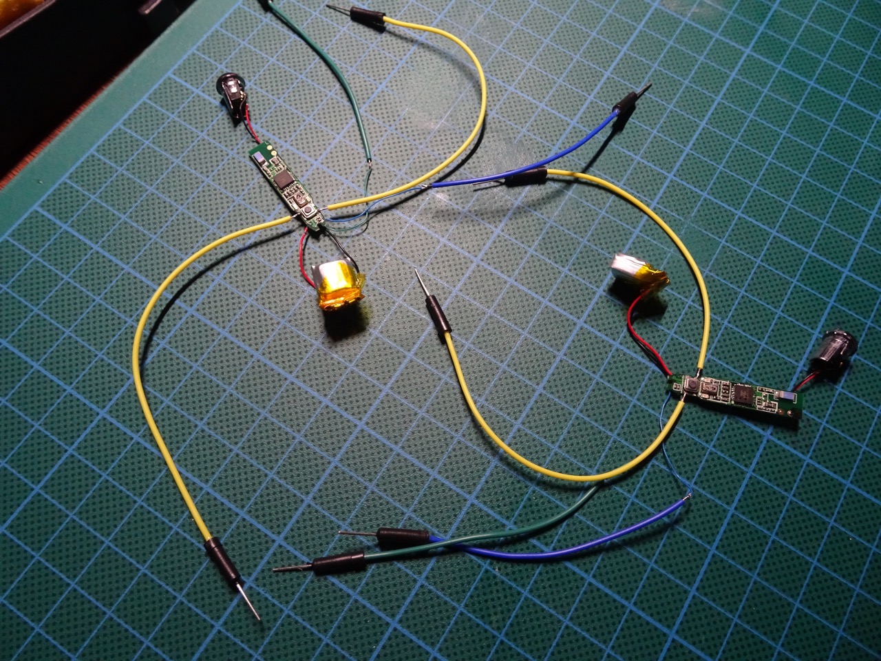
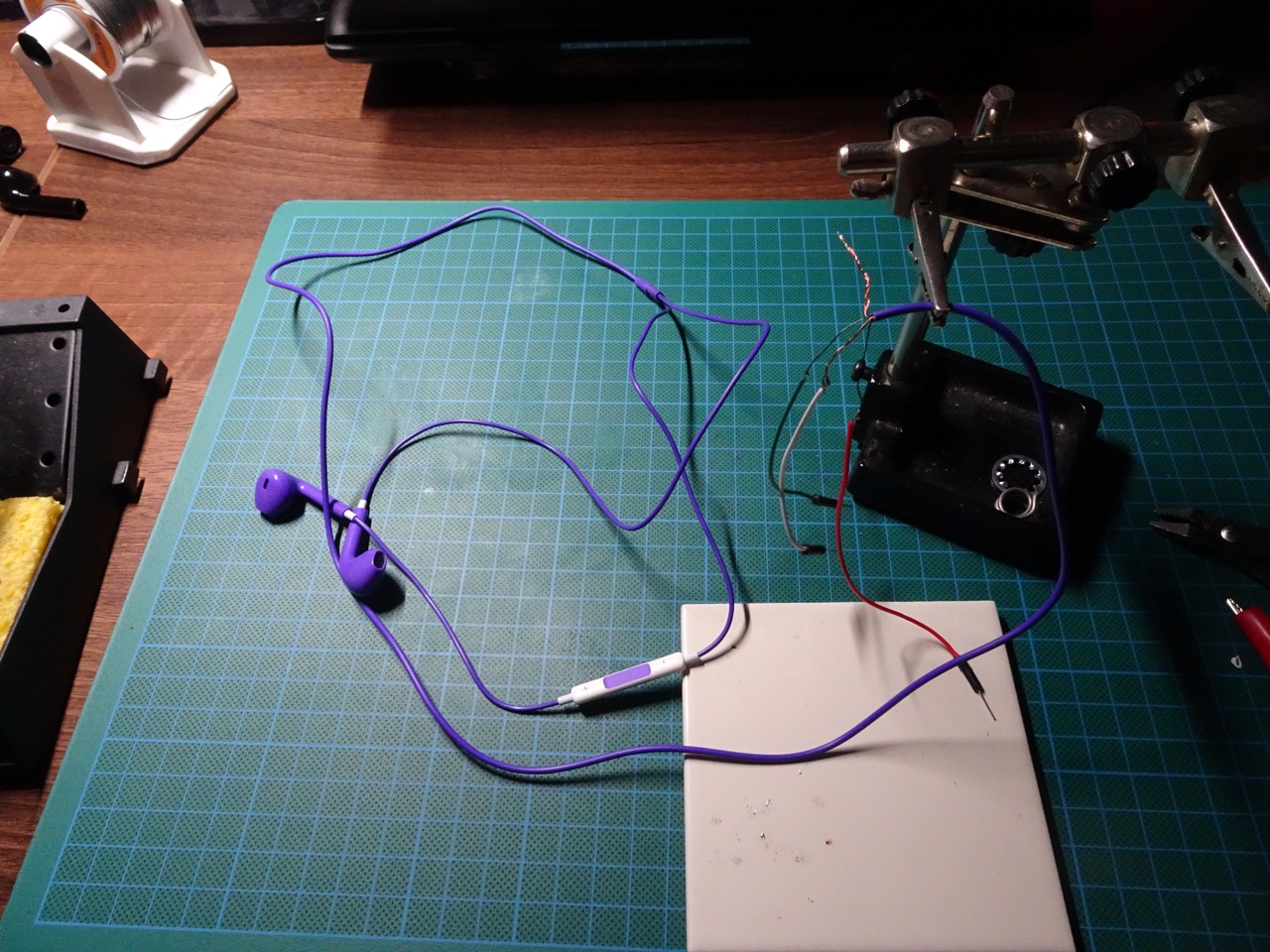
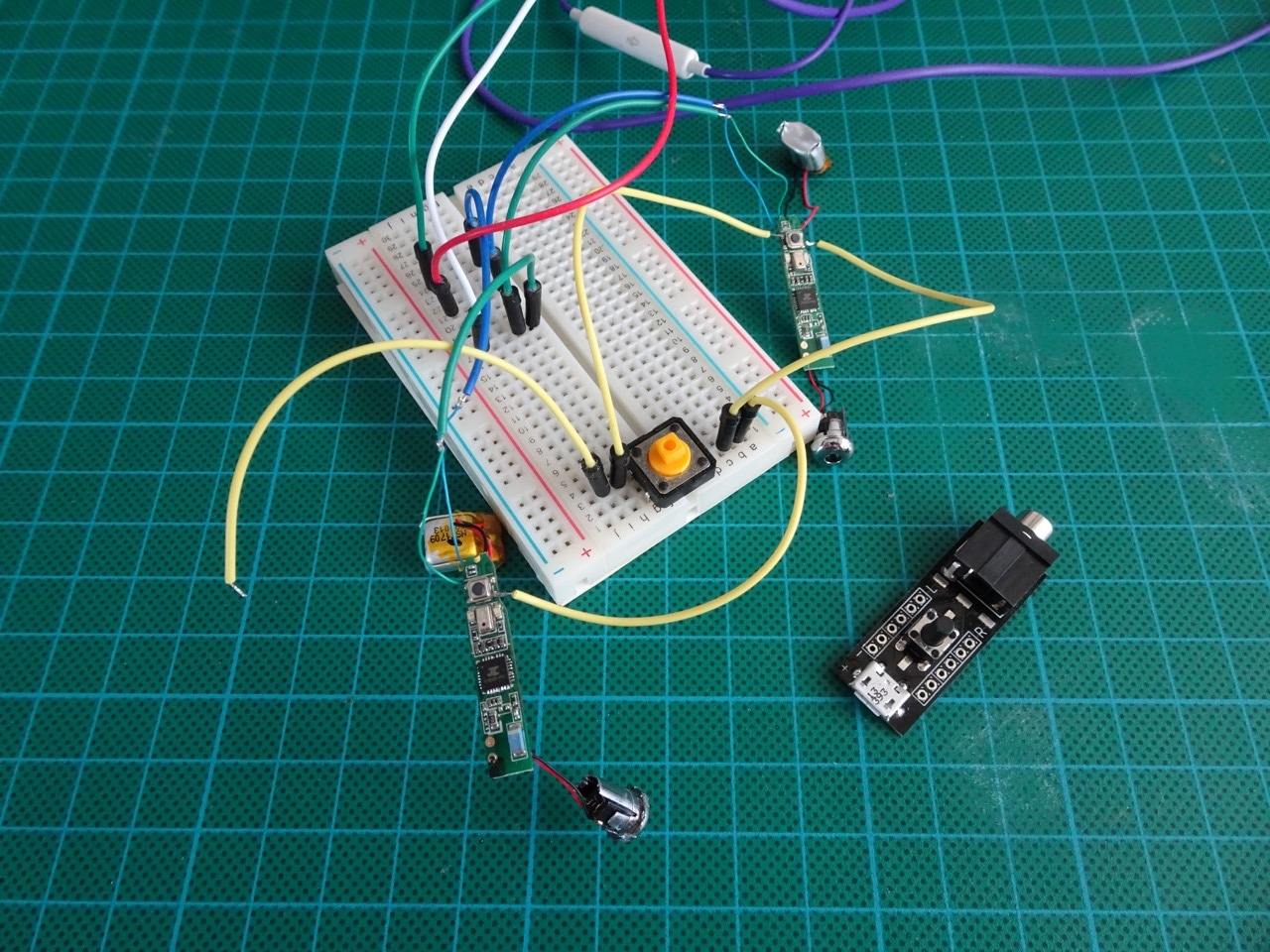
Before starting with any kind of custom PCB design I thought I'd try out my idea with a breadboard. This meant hooking up some jumper wires to the switches on the wireless headphones. I also needed to test if there was going to be stereo sound so I took apart a cheap pair of wired stereo headphones and hooked them up to jumper wires too.
I hooked everything up - one common switch and the audio wires hooked up to the stereo wired headphones.
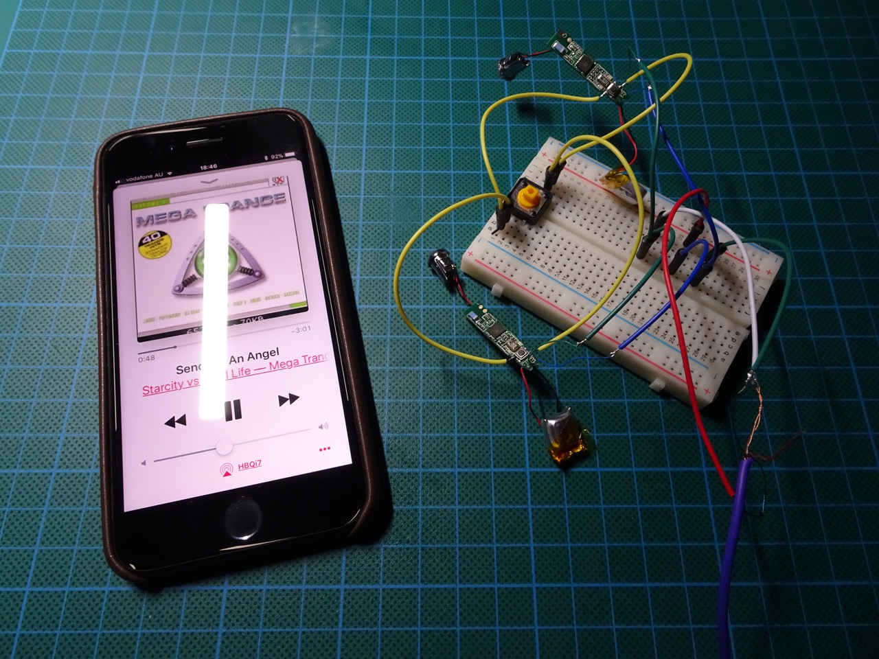
It actually worked! The single switch was able to operate both of the wireless headphone circuits and have them sync. This was encouraging so I put together a very simple circuit and sent it off to PCBWay for fabrication.
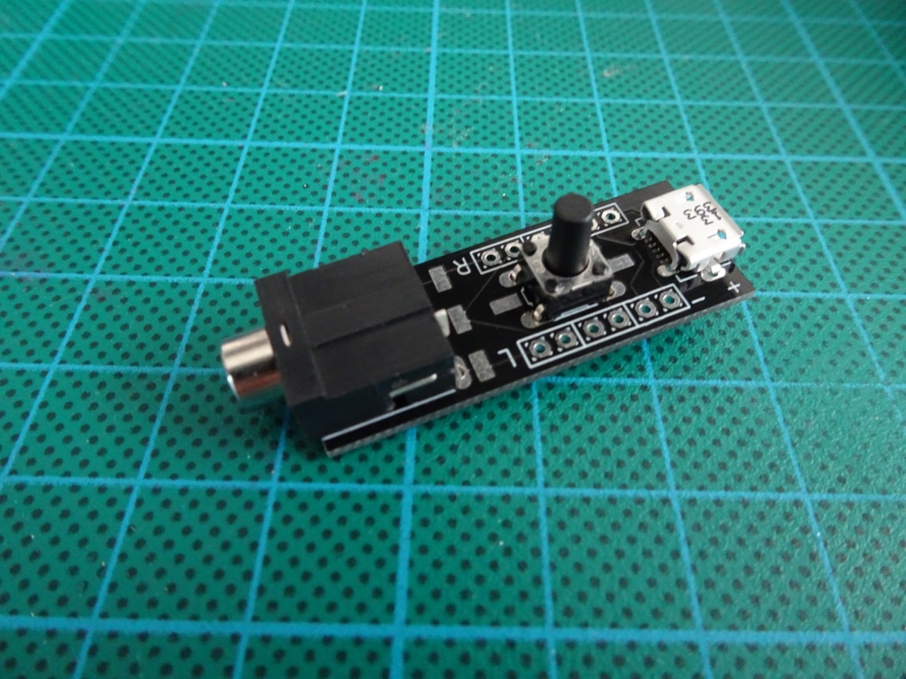
The circuit had nothing interesting about it really. It used an a micro USB receptacle for power (con-molex-usb 47589-0001), a momentary switch (switch-omron B3F-1000), and a stereo socket (con-lumberg KLBR4). Everything else were just pads and through-PCB holes. I put in a bunch of extra test pads in case I wanted to experiment later, these didn't end up being used.

A couple of weeks later my PCB arrived and all the parts were ready for soldering...

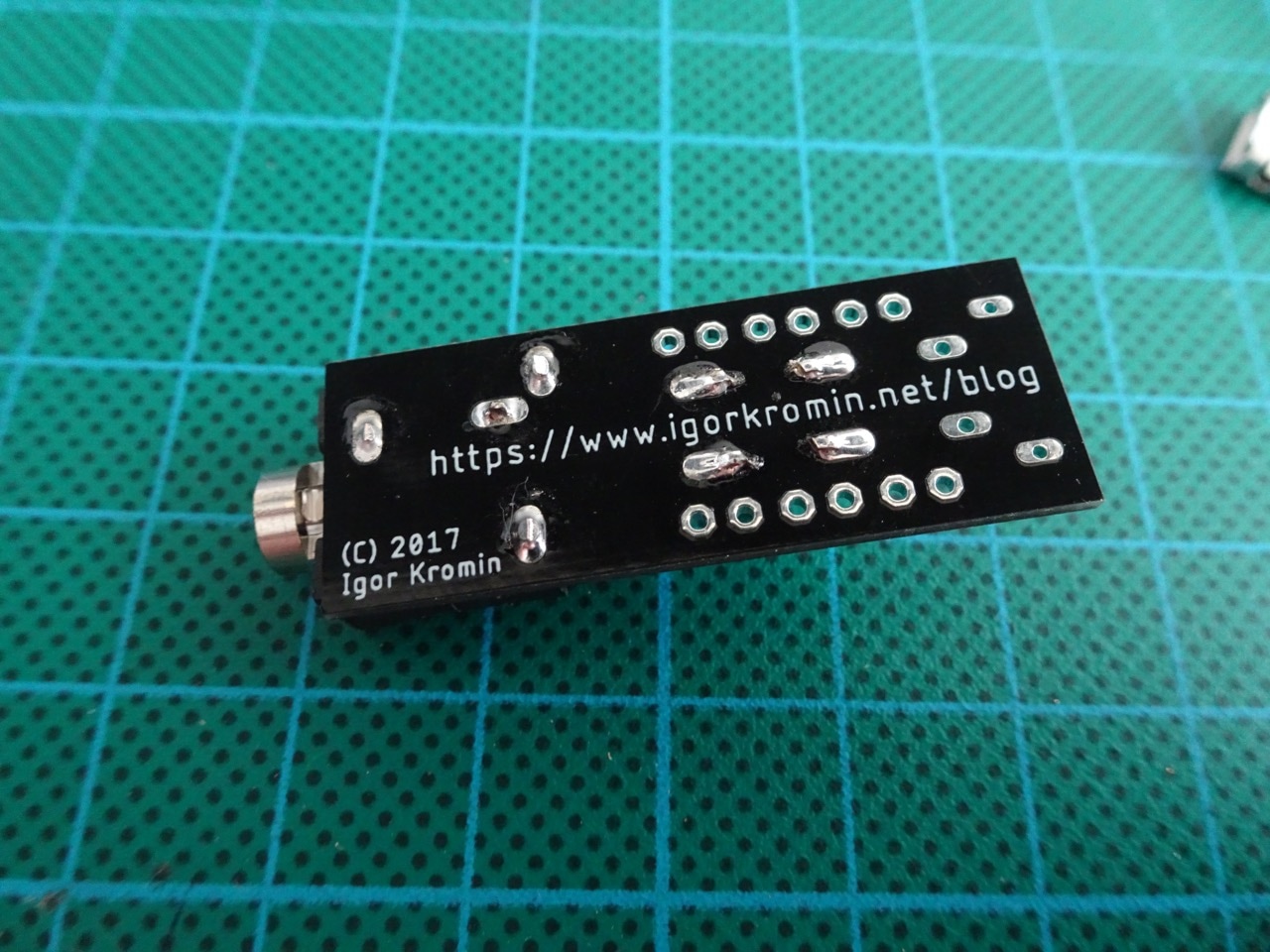
Some progress photos...
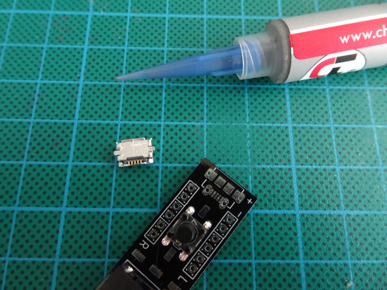
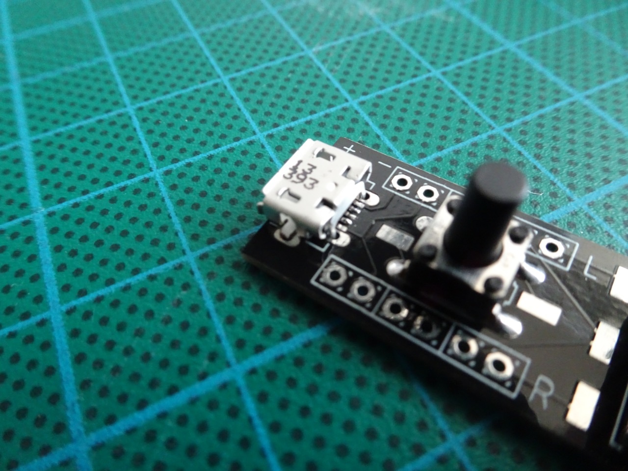
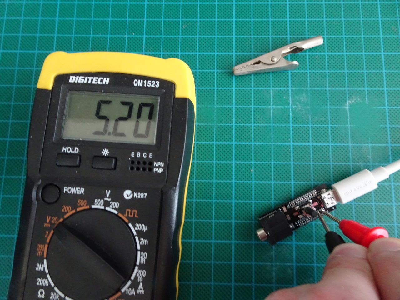
Making sure that I was getting 5V on the correct pins before soldering everything else (power and audio connections) in place.
Transplanting from the breadboard to the PCB was trivial and not long after I had both receivers charging, as expected.
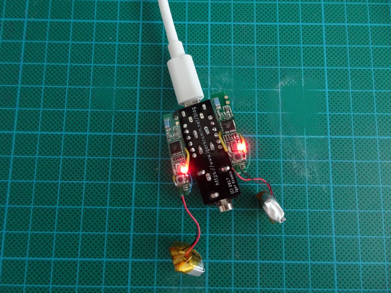
So at this point I was able to charge both of the receivers. When the microswitch was pushed down, both of the receivers activated and connected to one another and my iPhone, as expected. There were minor sync issues from time to time though - some of the time only one of the receivers would activate - I put this down to low battery charge.
So where to from here? Nowhere really! I don't plan to do anything further on this project but it was a fun experiment nonetheless!
Update: I used some left-over PCBs for another project... Adding a micro-USB power socket to an Atari Lynx.
Don't want to mess around modifying headphones or soldering? Spriee has an interesting article just for you - Best Studio Headphones 2020: Best Headphones For Mixing And Mastering.
-i
