First lets take a step back though. It all started when I wrote about Hacking the VideoPak 7inch promotional brochure to work as a digital photo frame. In that article I was able to get my own images (as videos) to display on the device, but also noted - So far so good, but unfortunately every time the device shut down after the last video has been played. Well I just could not let go of this project and not having reused the brochure in some way would have been a total waste of resources used to create it.
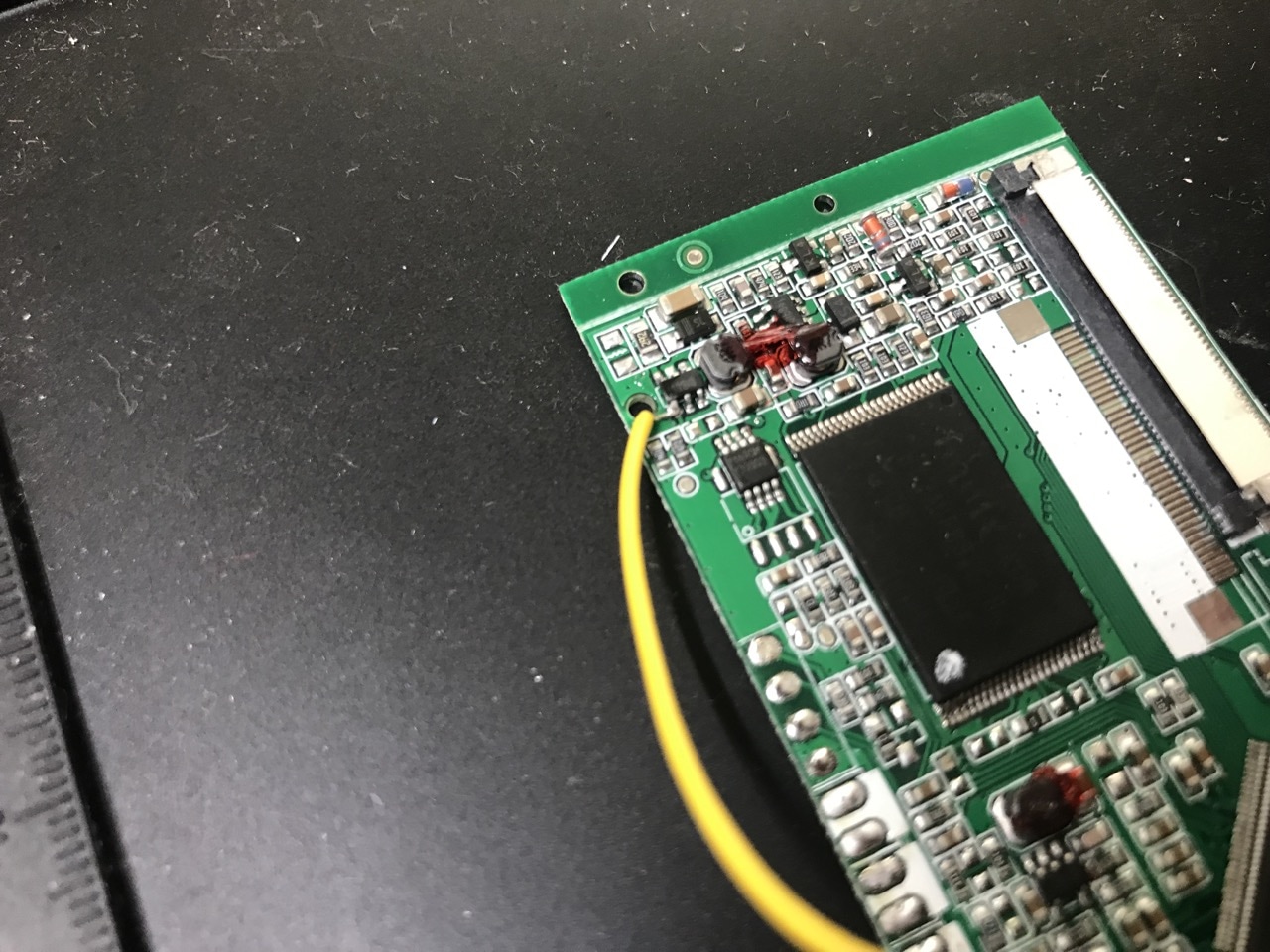
What I needed to do was somehow force the magnetic switch to trigger when the device finished displaying all of the videos. Since the device would turn off once all of the videos have been displayed, its screen would be off too, so I figured that I could make use of that. After looking around and probing the controller board, I found that a 6 pin chip labelled B1B86j (apparently a DC voltage regulator) had one of its pins fall from high to low whenever the backlight to the screen was turned off. This gave me an idea. I could monitor this pin and then when I detected it going low, I could do something on the magnetic switch side.
On the magnetic switch side I noted that it would usually be pulled high when videos were running. It wasn't enough to pull it low to trigger however, I had to pull it low, then pull it high. When that was done, the device would reset. Progress!
I still had the issue of what to do with regard to power. The micro-USB connector that was part of the brochure had undesirable behaviour - whenever power or a data connection was made, the device would go into charge or external USB storage mode and would not display videos. This meant that I couldn't simply connect external power to this port and be done with it and since I had no way of changing the firmware, I was forced to find another way around this.
The battery presented an opportunity. I noted that if the battery was disconnected and around 3.7V was supplied to the PCB via the original battery pads, the video brochure would quite happily run as normal. The only catch was or course that I couldn't now use the micro-USB connection to "charge" the device. I had a couple of WeMos D1 Mini battery shields around so that's what I used to supply power instead of using a battery.
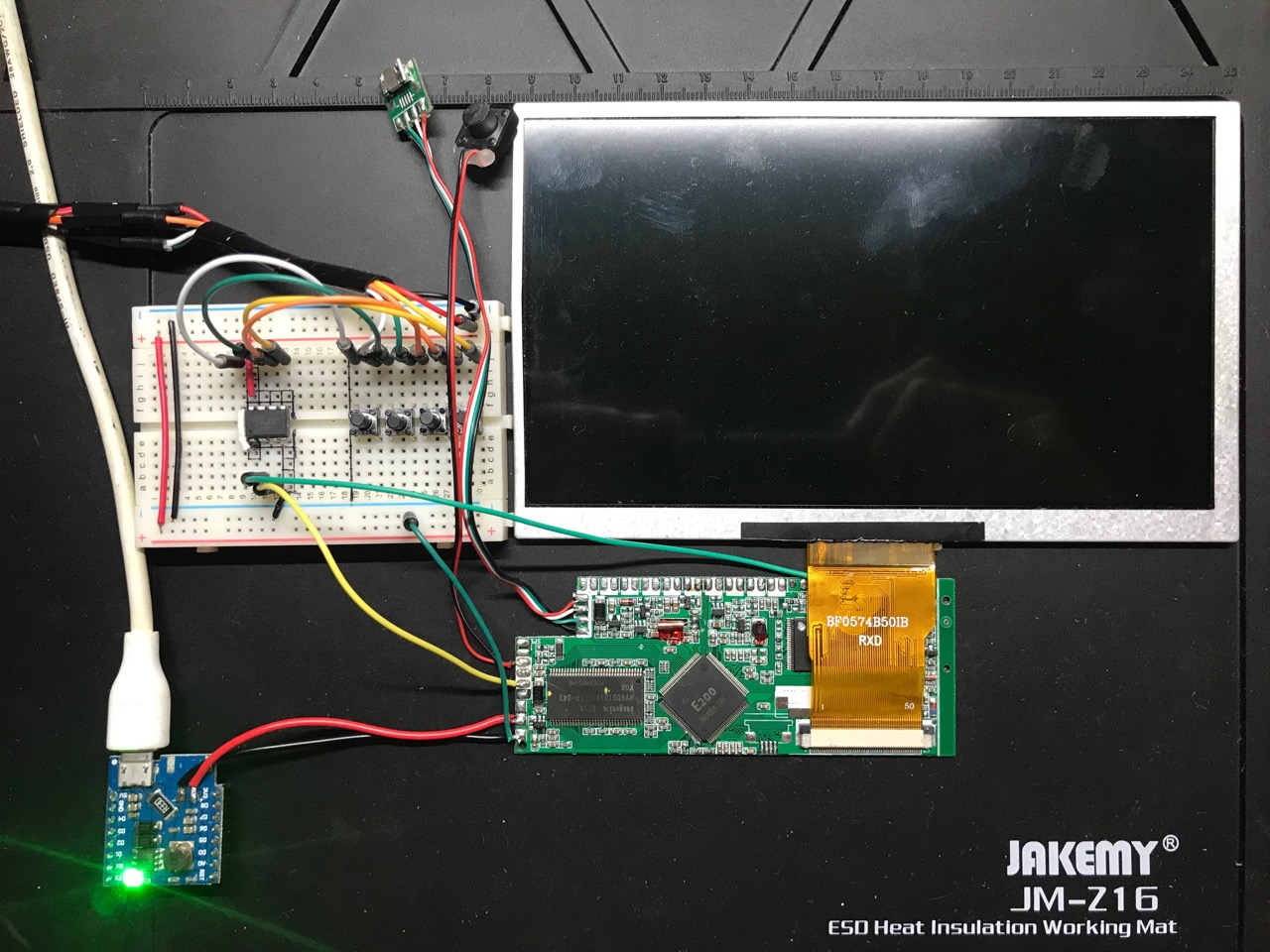
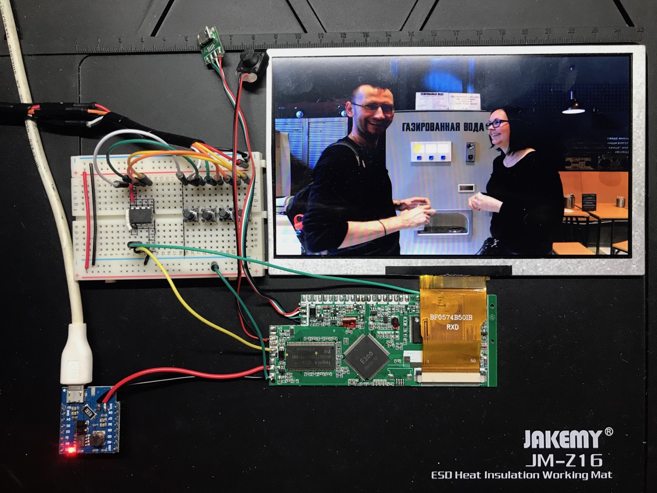
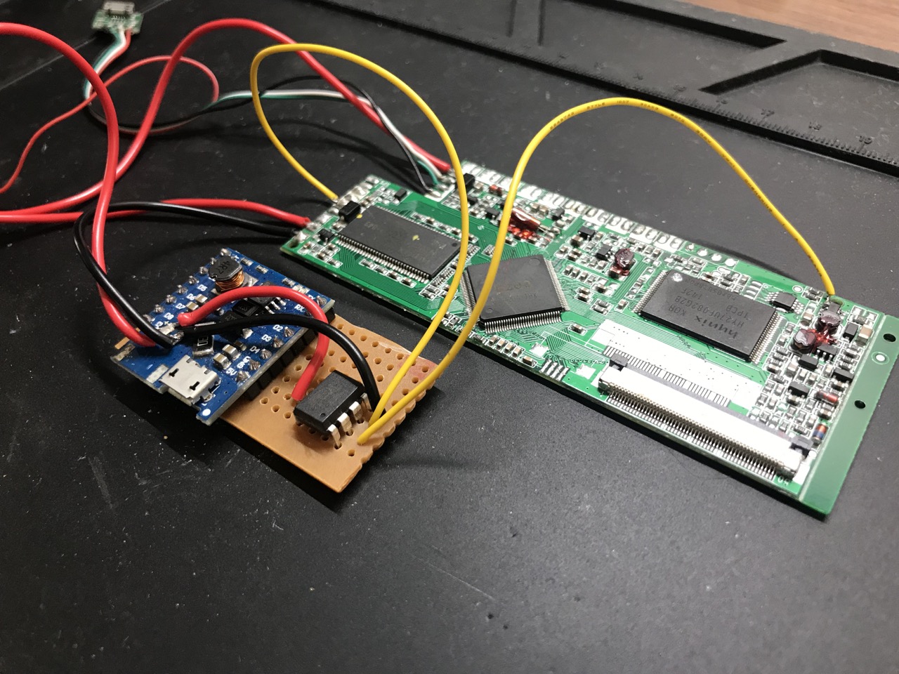
To tie it all together I used an ATTINY85 to control all of the monitor and trigger logic. I used a breadboard to get the basic circuit set up and it worked! Power was on, whenever the video brochure would turn off, the ATTINY85 would detect that and trigger the pins where the magnetic switch was, which would cause the video brochure to turn on again. This would repeat over and over as long as power was supplied - just what I was aiming to achieve.
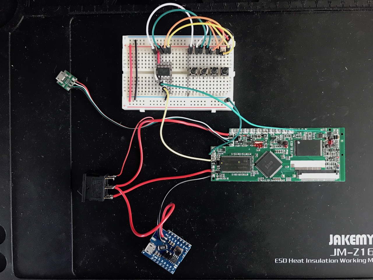
I then added a switch to allow me to select between the original micro-USB connector and the new one that supplied power. The original one in this case would only work for data transfers. Charging would not work since the WeMos module would be disconnected via the switch. When the switch was in the other position, the WeMos module would supply power and the power line from the original micro-USB socket would be cut.
The unit that was being built was going to PRGE 2019 as a display unit, so I couldn't keep it on a breadboard. I used a PCB strip board to house all of my components and the ATTINY85 was hooked up the the WeMos module for power at the same time.
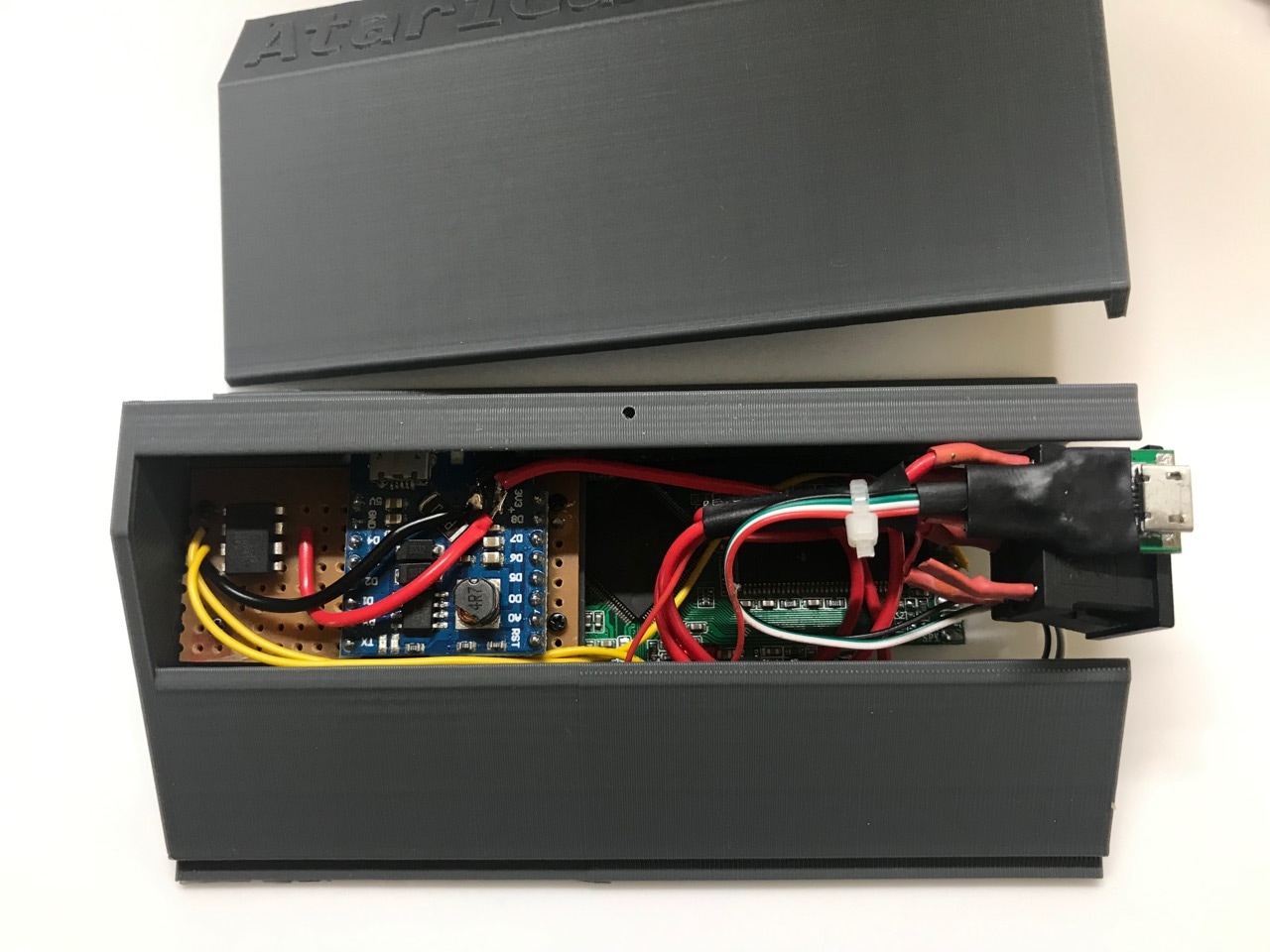
A shell was 3D printed to house all of the electronics and the display unit surround was laser cut.
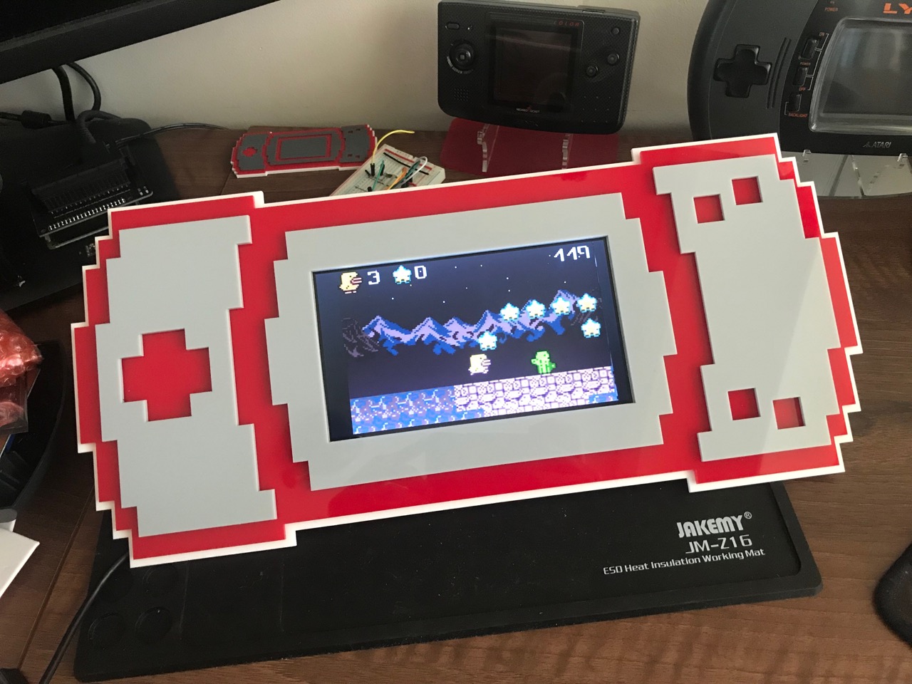
Here's a video of the unit in operation...
For anyone interested in the code used on the ATTINY85 here it is below...
C
#include <util/delay.h>
#define IN_MONITOR_PIN 3
#define OUT_TOGGLE_PIN 4
#define DELAY_MS 2000
void setup() {
/* pin for monitoring signal */
pinMode(IN_MONITOR_PIN, INPUT);
/* toggle switch pin initialised to be 'off' */
pinMode(OUT_TOGGLE_PIN, OUTPUT);
digitalWrite(OUT_TOGGLE_PIN, HIGH);
}
void loop() {
if (digitalRead(IN_MONITOR_PIN) == LOW) {
digitalWrite(OUT_TOGGLE_PIN, LOW);
_delay_ms(DELAY_MS);
digitalWrite(OUT_TOGGLE_PIN, HIGH);
_delay_ms(DELAY_MS);
}
}
-i
