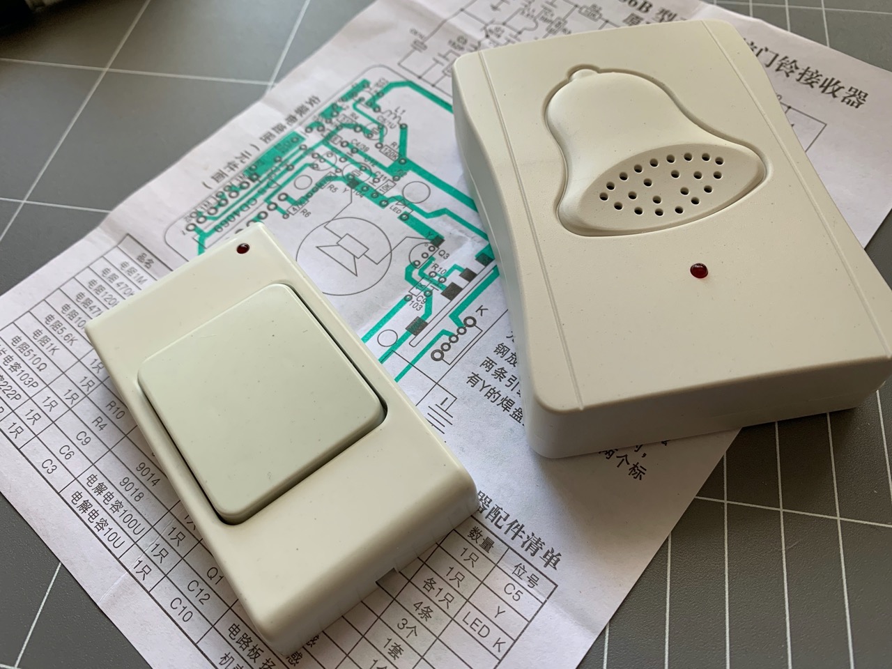
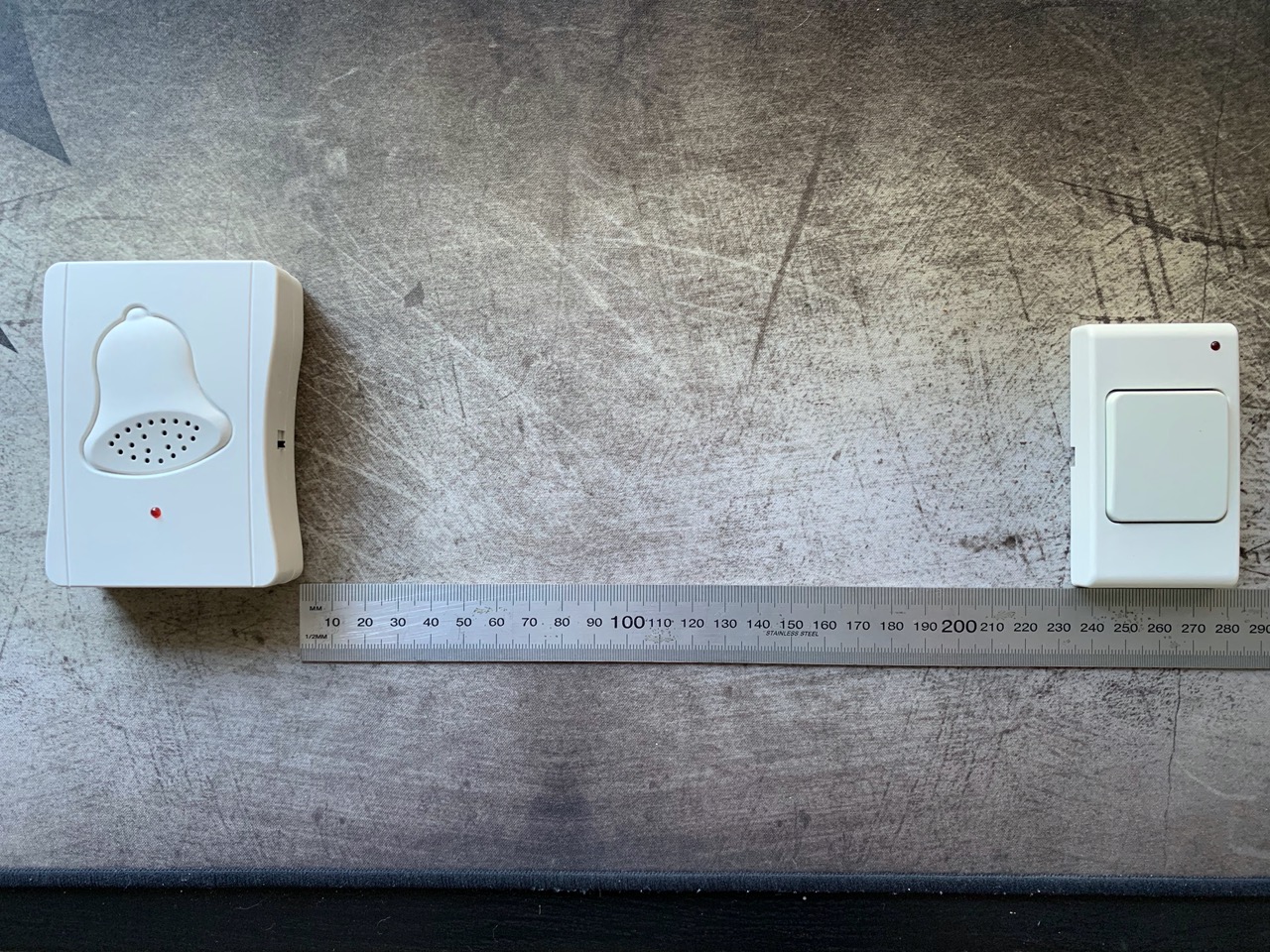
I was actually quite looking forward to putting this kit together because so far in this house we don't have a doorbell installed. Unfortunately it will remain so because the wireless range of this kit is really not suitable for every day use, more on this later.
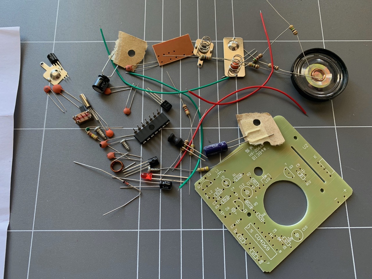
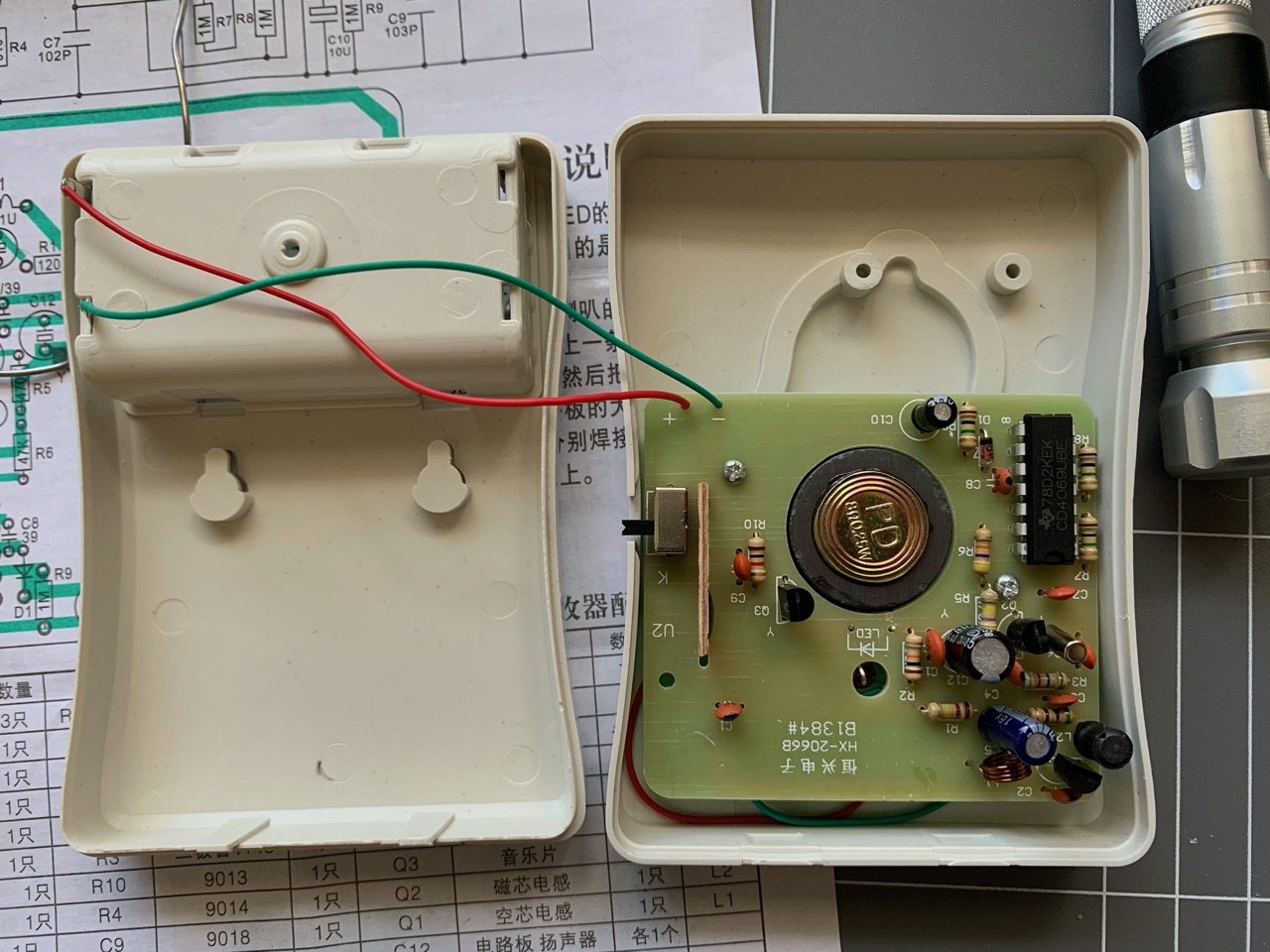
Overall the kit is a decent started kit, especially if you are learning how to solder and want to experiment with soldering all range of components from resistors to ICs to custom "black blob" breakout boards. There are a total of 3 PCBs included, one for the remote button, and two for the bell itself - this includes the main bell PCB and an additional breakout board that houses a custom IC.
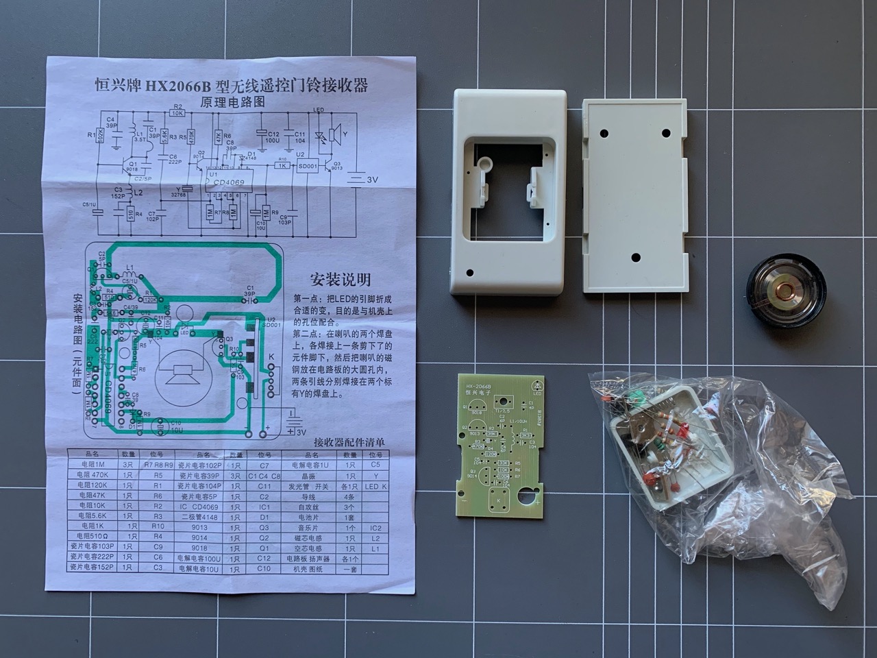
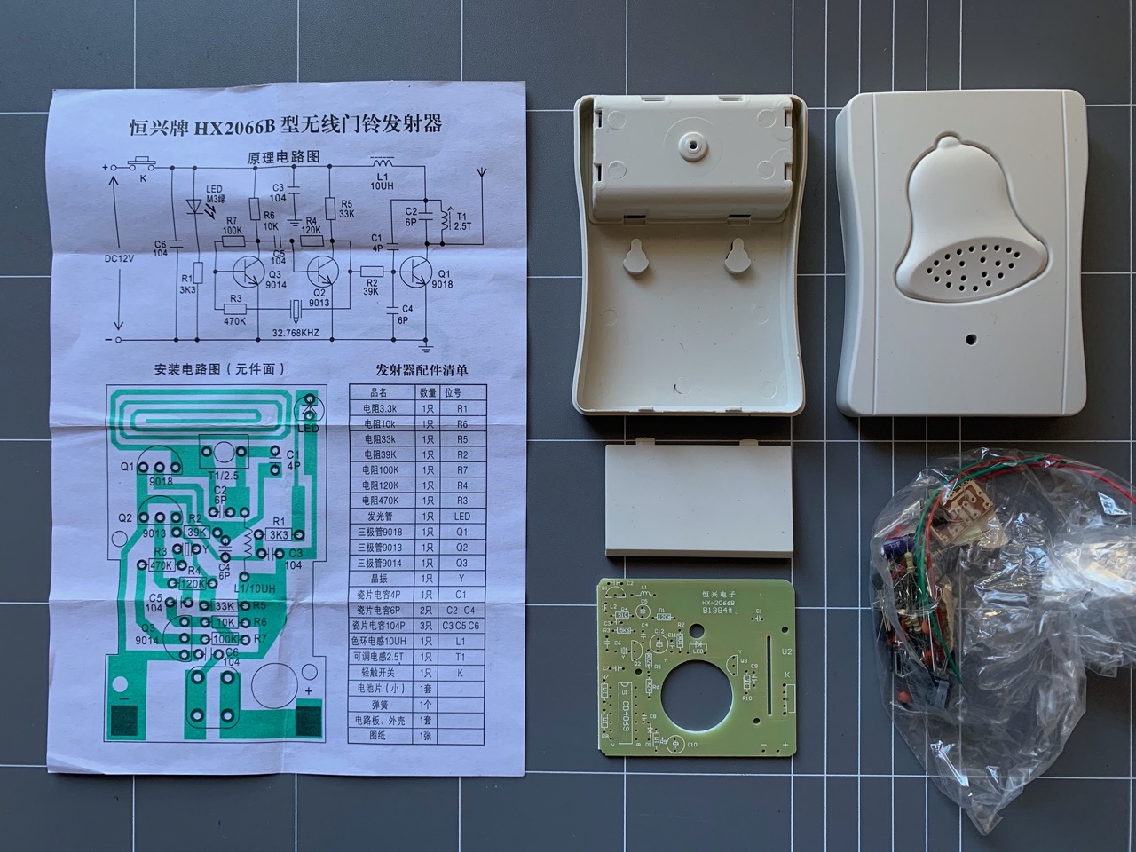
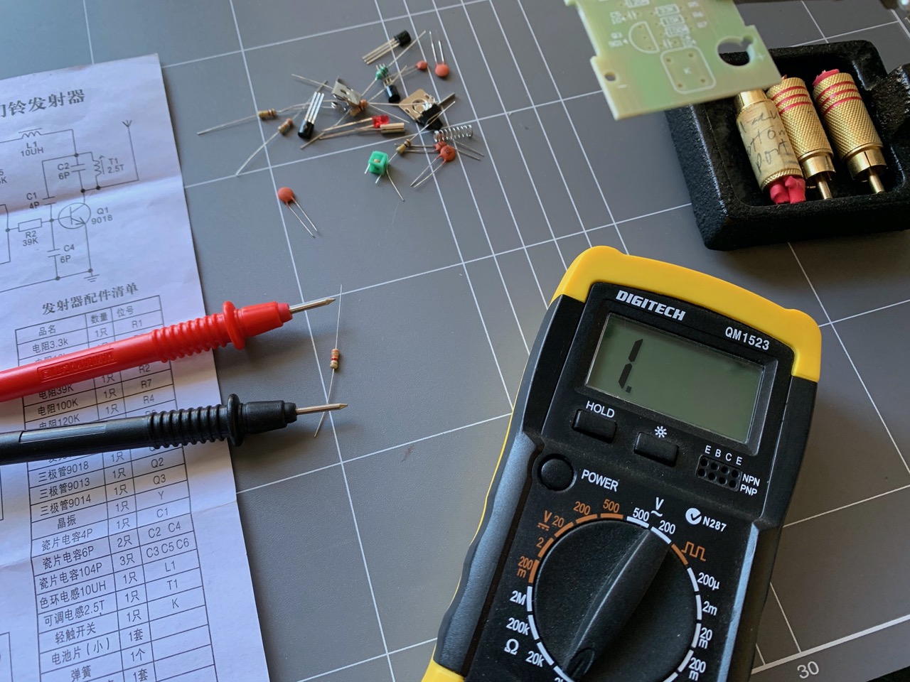
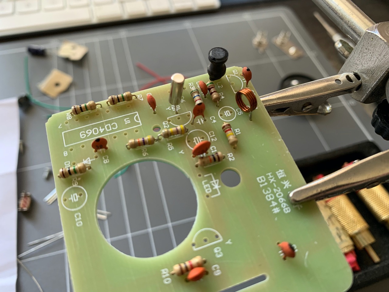
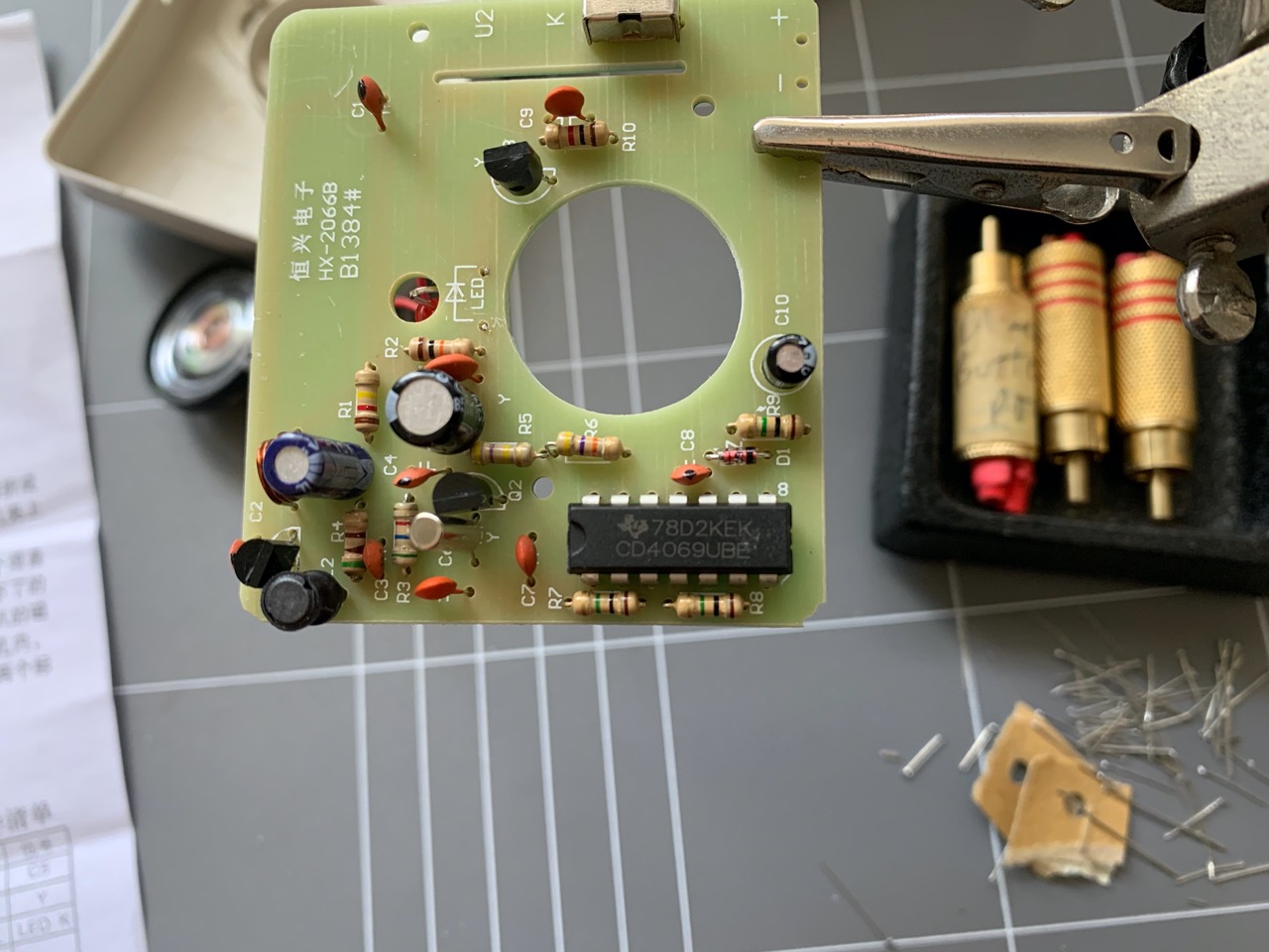
So let's see what was included. The plastic housing for the remote button and bell were part of the kit. All the components required to put both PCBs were there, the only part that was missing was one small screw to keep the button PCB in place inside its housing - which wasn't a big deal. There was a single sheet of A4 paper with "instructions" in Chinese (Mandarin?) and the PCB layout and circuit diagram. The parts list was also included but was of little use. The button PCB had all of the component values printed on it, but the bell PCB didn't, so I had to rely on the circuit diagram to work out values of some of the components. This was fairly trivial.
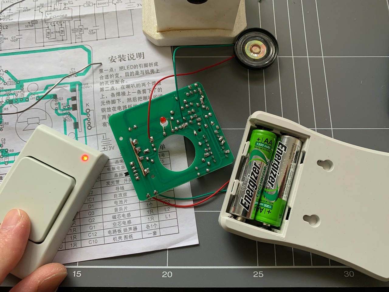
No batteries were included in the kit. The bell required 2x AA batteries and the button required a single 12V A27 battery.
I started with the remote button PCB first. Resistors were first to be fitted. I didn't really love the quality of the included resistors as their colour codes were hard to read and washed out in places. So, I used my multimeter to measure their values to be sure.
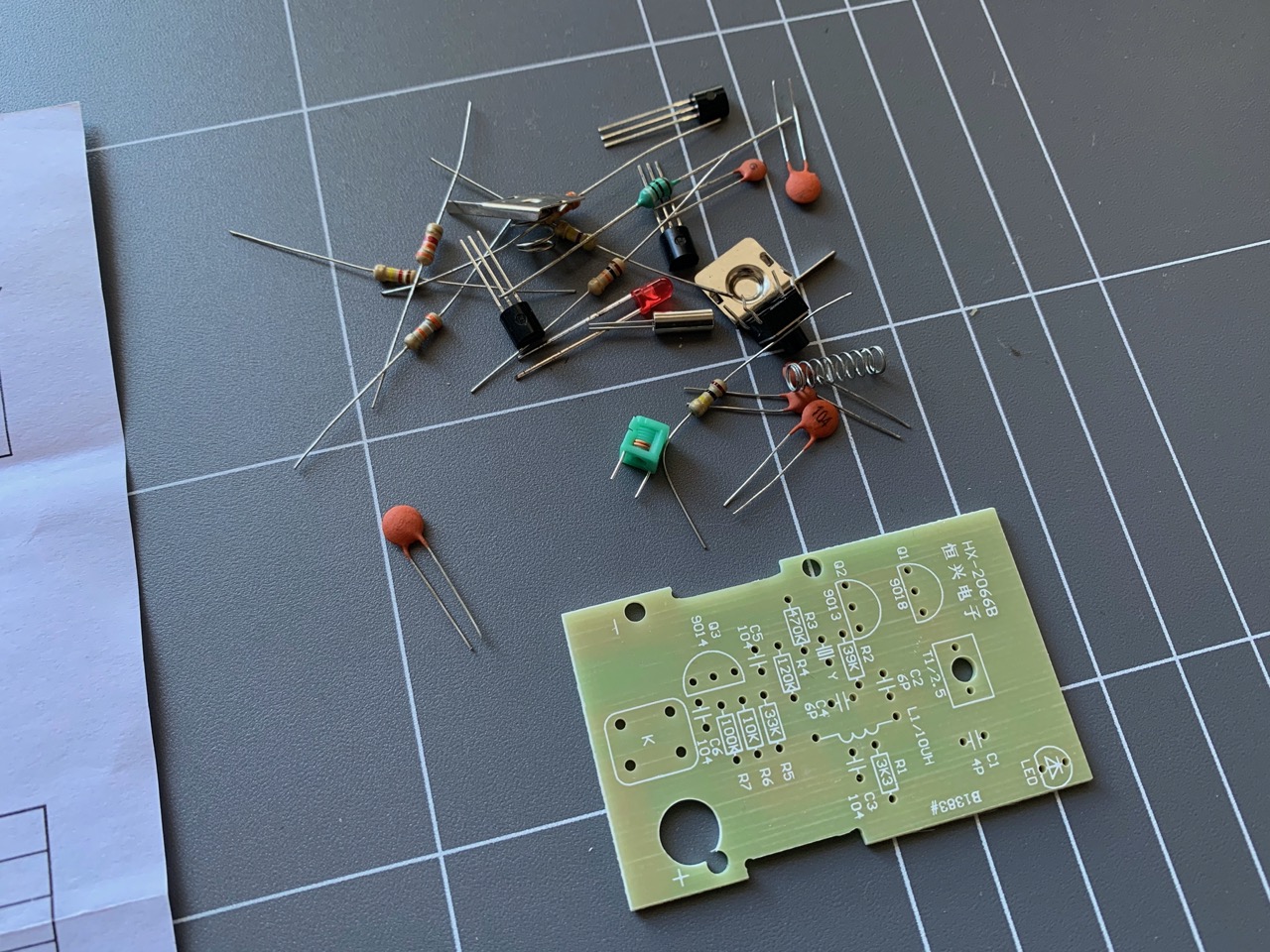
The side cutters I mentioned earlier were perfect for snipping off the legs of components after soldering. I'm still amazed how cheap they were. I did mention that the spring felt a little weak in these cutters in my first article on Digitspace, but this was really not an issue when actually working with them. The main point was that they are sharp and cut well. With the legs snipped off, all the resistors were in place.
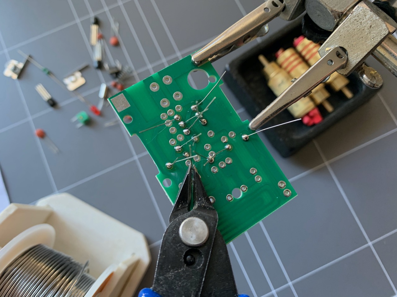
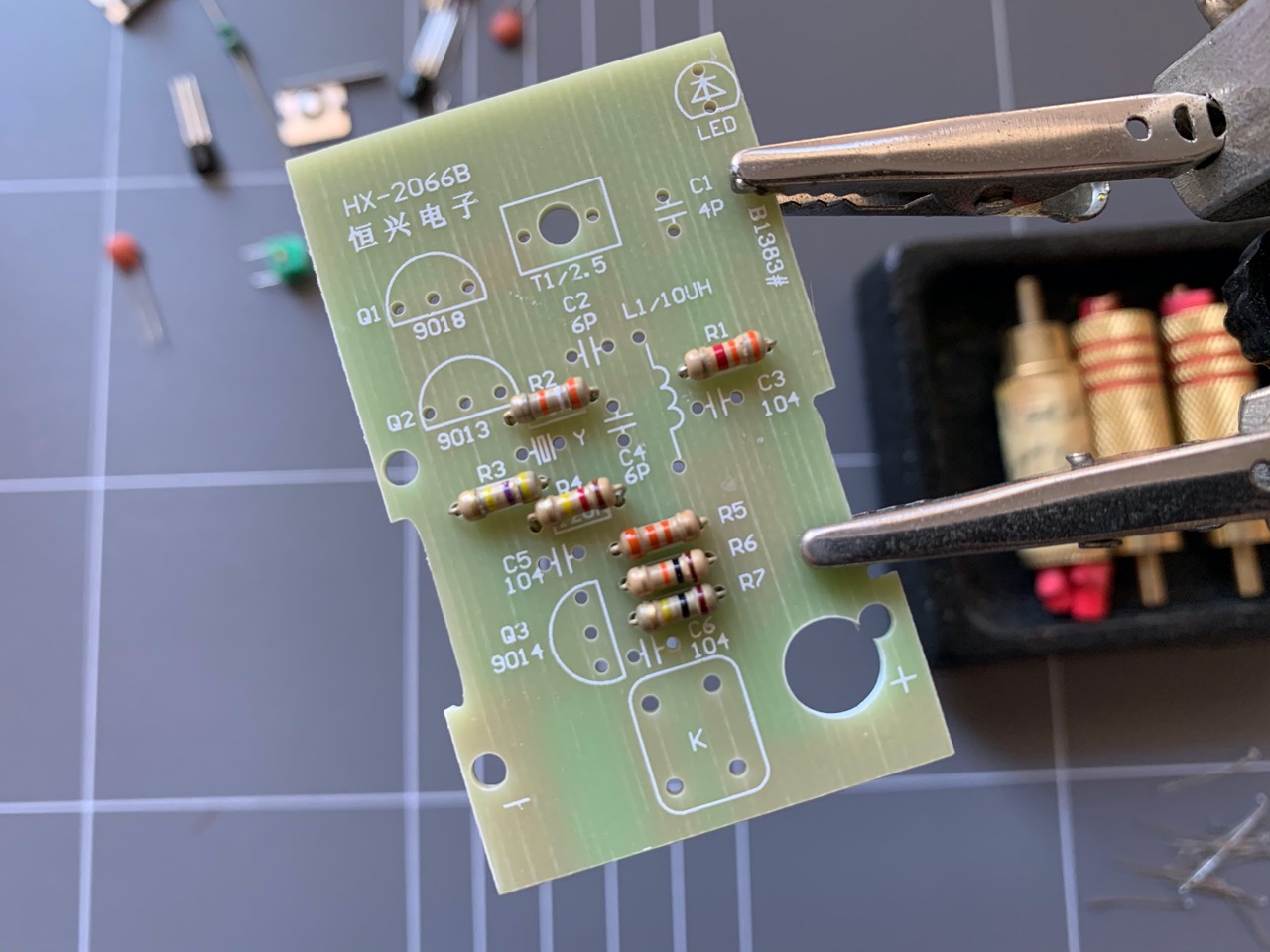
The coils and crystal were next in, followed by the transistors, LED and button. The button was easy to orient as it had a rectangular shape and fit in one way only. The LED's legs needed to be adjusted to the right height relative to the case so it fit the hole cut out for it.
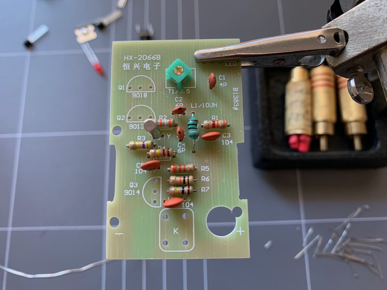
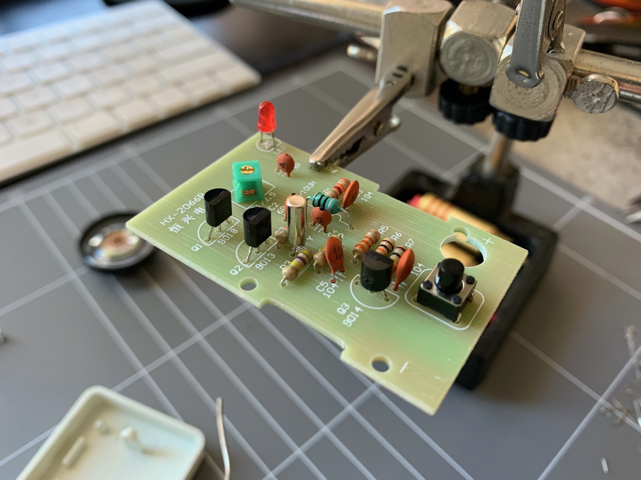
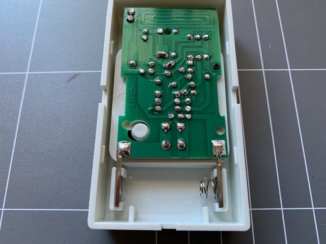
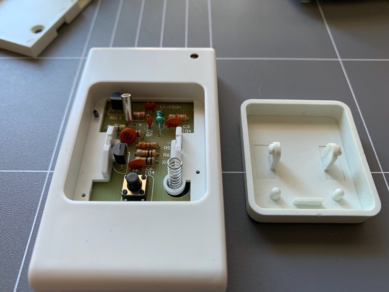
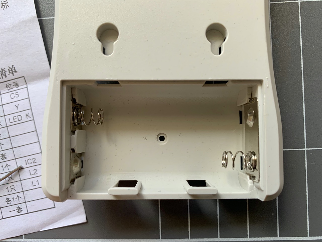
The battery terminals were soldered in after I placed the PCB into its housing. The terminals slid into grooves of the housing. On the other side, the button was spring loaded and had some plastic clips it slotted into. The spring was a little bit tricky to line up.
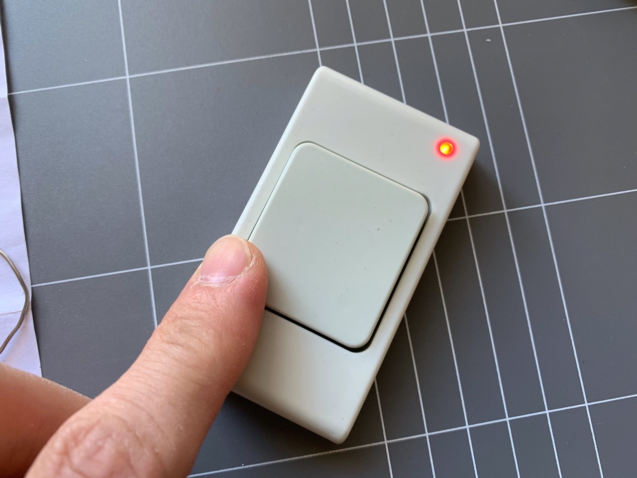
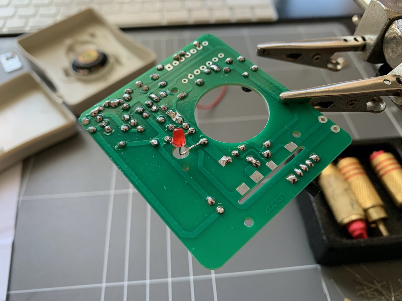
With everything assembled, it was time to see if it worked...and I had the LED lighting up, of course I needed the bell part assembled to test this further.
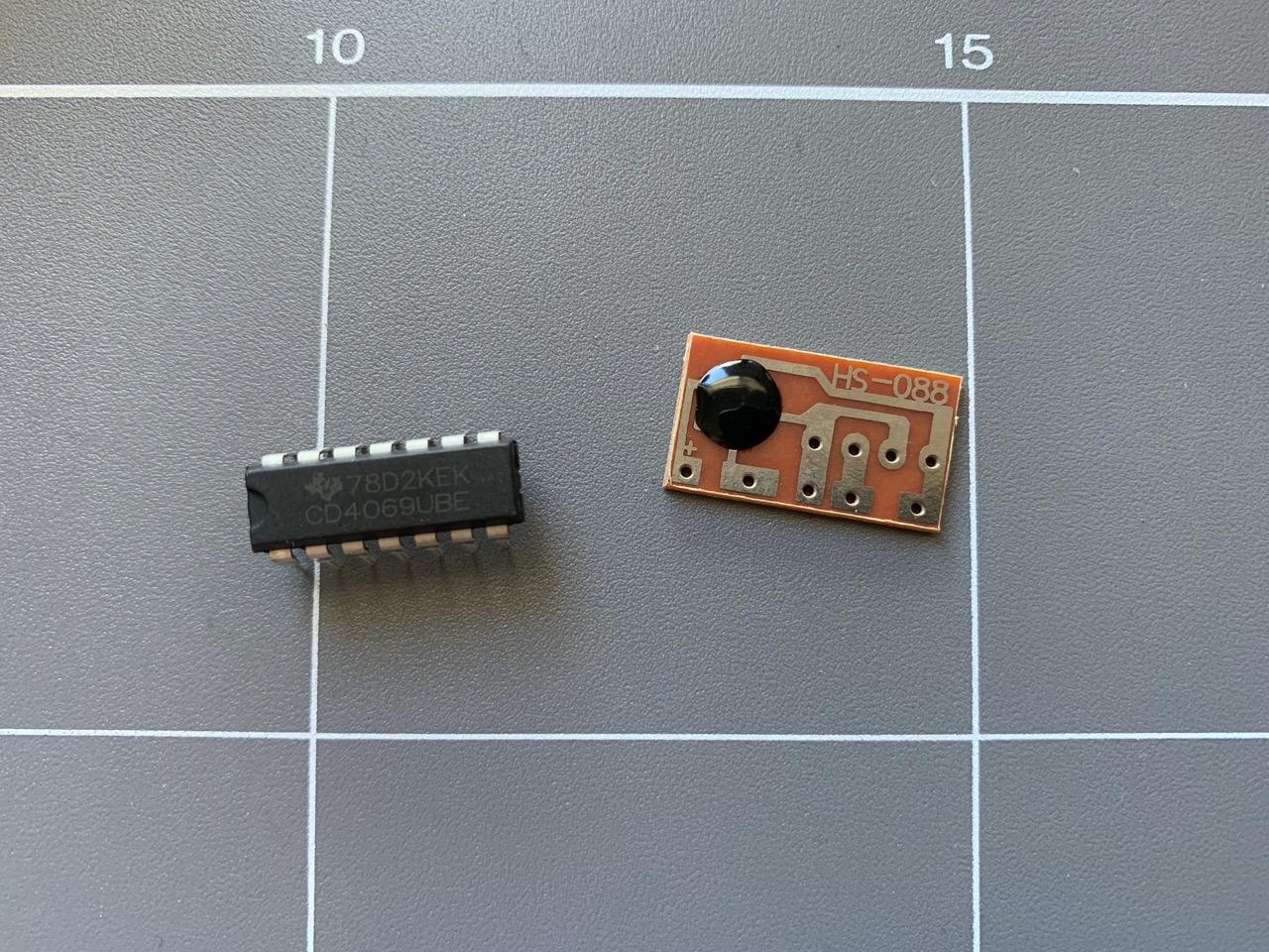
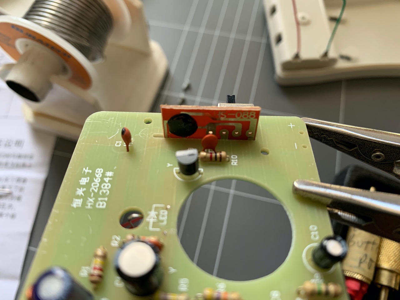
The bell PCB assembly was next. There was an IC and a breakout board included that housed a "black blob" IC. I was a little confused about how this would fit at first but it turned out that this was quite easy in the end, more on how it was soldered in later.
Resistors and ceramic capacitors were installed first. Followed by the coils, crystal and electrolytic capacitors.
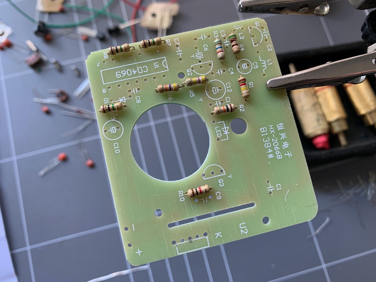
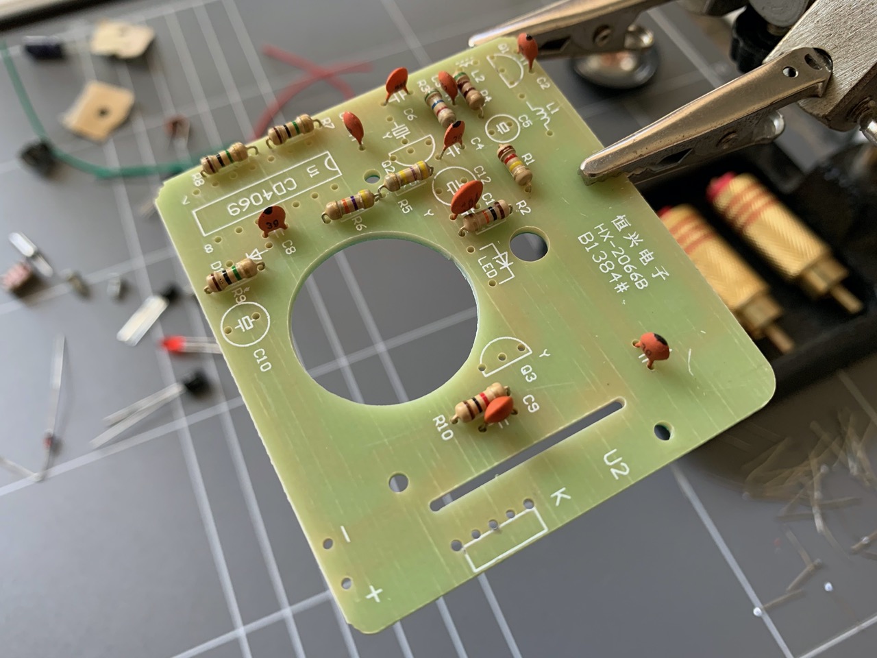
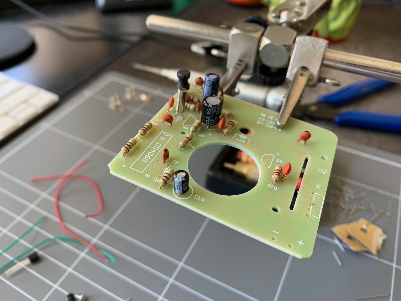
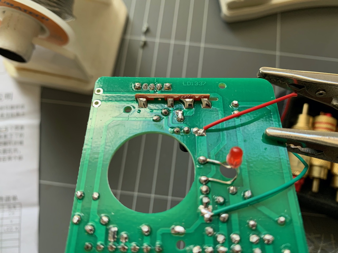
Transistors and switch were next up, followed by the LED, which had to be mounted on the opposite side of the board and its legs adjusted to suit the LED hole in the case.
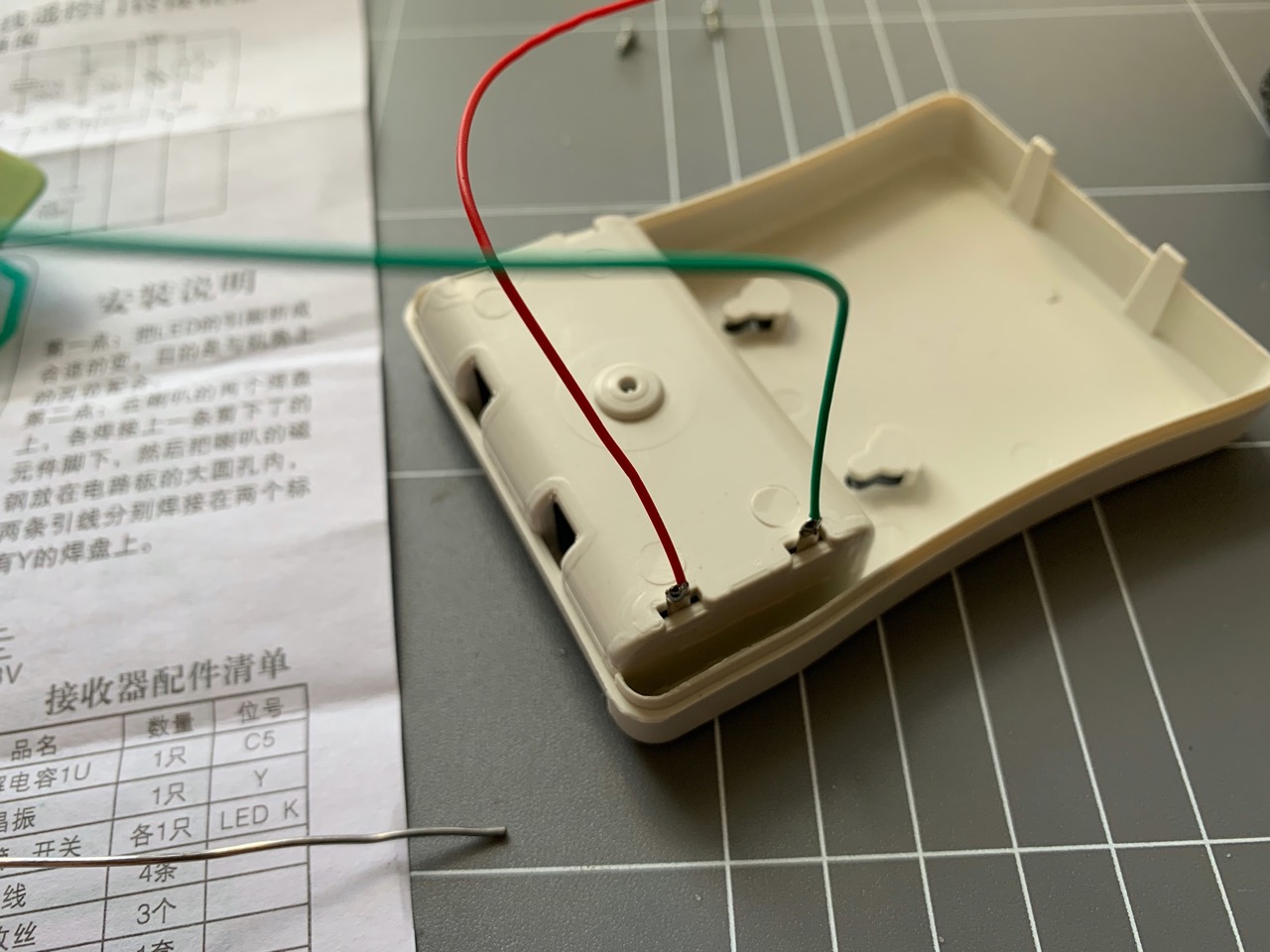
The battery terminals were different in this enclosure, there were 3 of them instead of two, that was because there were two batteries. They slid into the enclosure a similar way but had wires that needed to be soldered to them, connecting to the PCB. The speaker was soldered in next. It didn't seem to have any polarity markings so I just used whatever left over wires to connect it up. The PCB side of the speaker wires were connected to some pads on the bottom side of the PCB, there was no hole/via for these wires so I had to use the circuit diagram to work out where exactly to connect them.
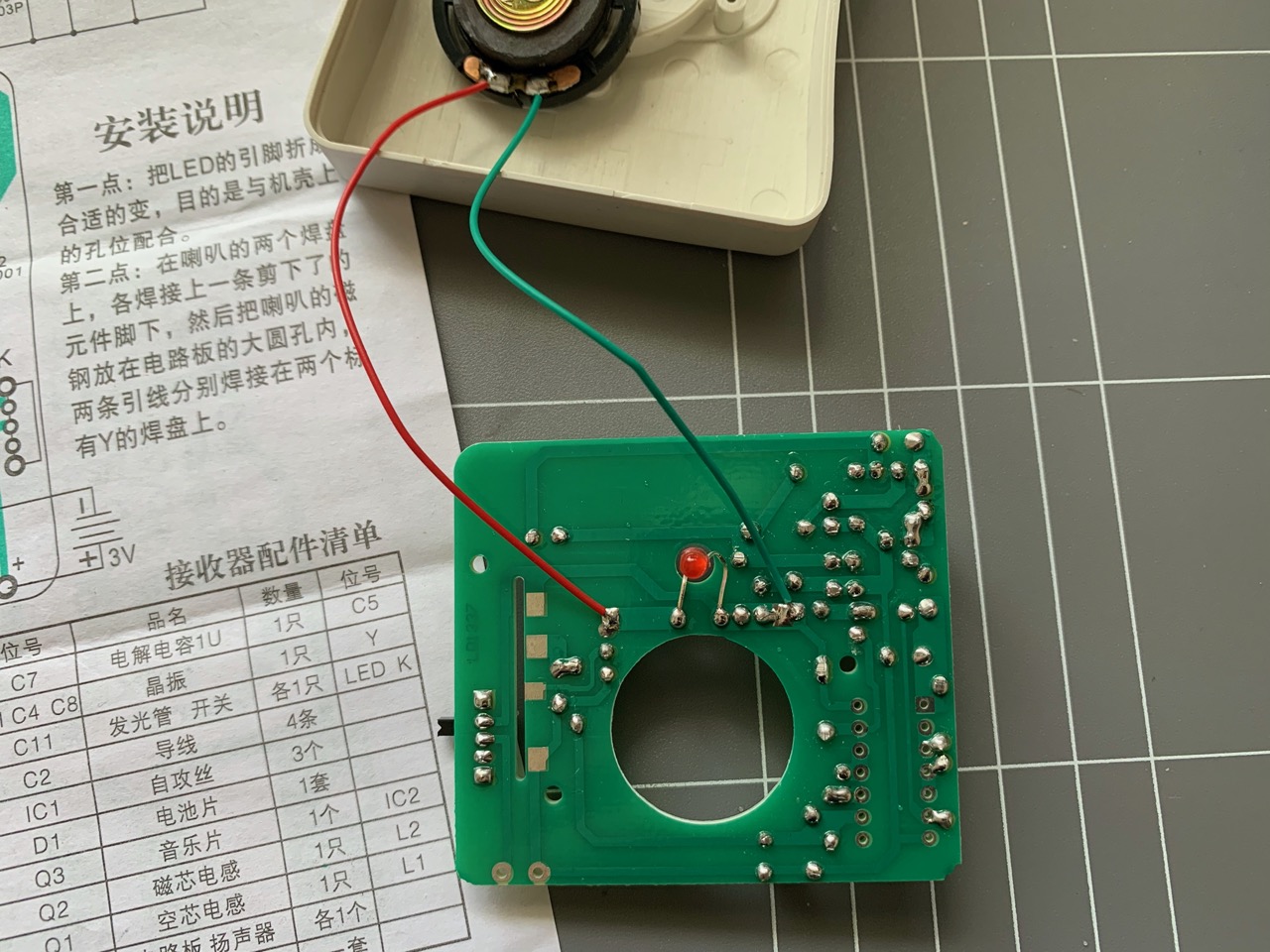
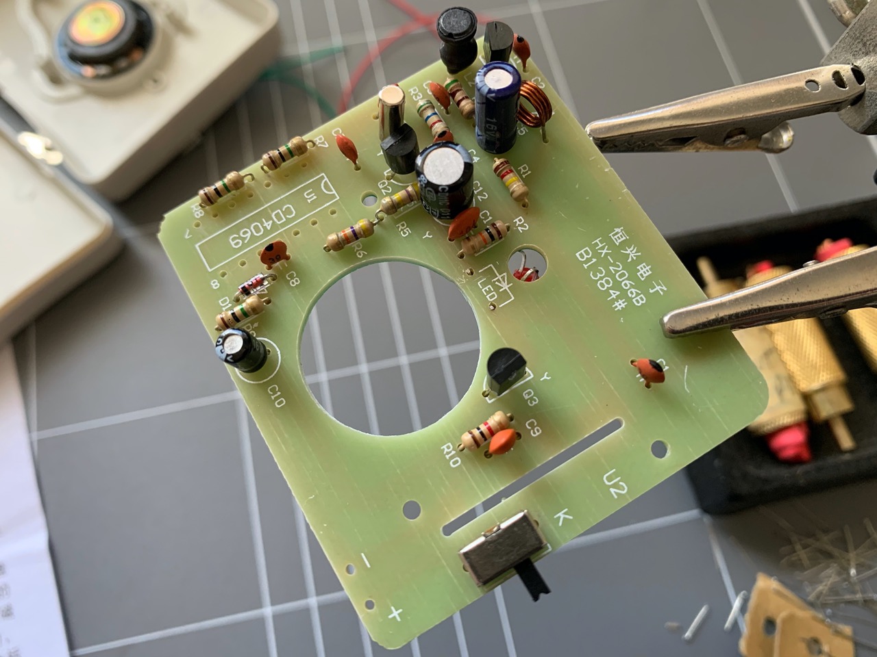
The ICs were soldered in last. The big 14 pin IC was in first of the two. I bent its legs to shape before sliding it into its place on the PCB and soldering it in. The "black blob" IC with its breakout board went in last. There was a slot cut into the main PCB for it and pads on the bottom side that could be used to connect the breakout board. These pads lined up to the breakout pads and I just used a blob of solder on each one to connect them. Only 4 of the pads were connected, one had no corresponding pad to solder onto. I also soldered in the battery wires at this point.

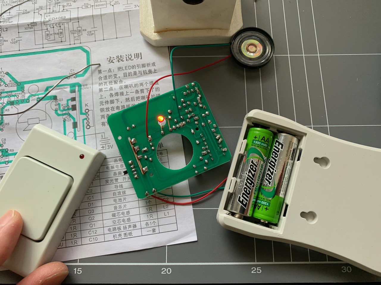
Testing both parts of the kit out...I got a sound when the button was pressed!
Next I put the bell casing together with the PCB secured inside and that was the end of the assembly.
As I mentioned earlier, this kit has bad wireless range. In fact, the furtherest distance I could get the button to work (sometimes) was about 23.5cm when both the button and bell were laying on my desk. I tried using it through a wall and there was no signal penetration at all, so using it on the outside of a door was not going to work. There's probably some tweaking possible, especially with the adjustable coil on the button PCB, but that's not something I tried. I may still use this in the future, but wire it up with a physical connection between the button and bell.
The sound of the bell is a fairly generic, but rather annoying beep-bop, not really a ding-dong. Still it's a nice kit to put together if you're doing it just for fun and know that it won't be very useful in the end.
-i
