The plan for building this enclosure was to make a part MDF, part fibreglass box with front and rear sections made out of MDF, an MDF frame and the rest fibreglass. In hindsight I should have used MDF for all sides and just reinforced with fibreglass inside.
The first thing I did was make a template for the front face out of cardboard.
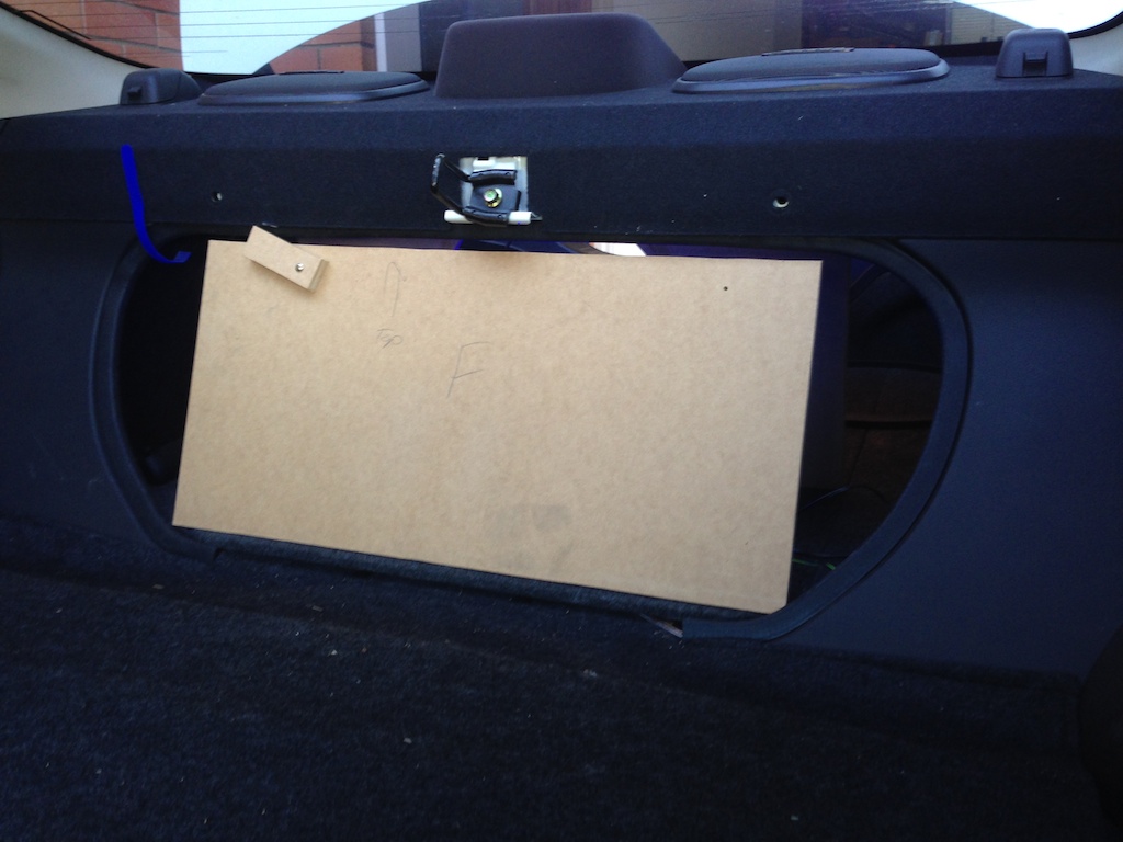
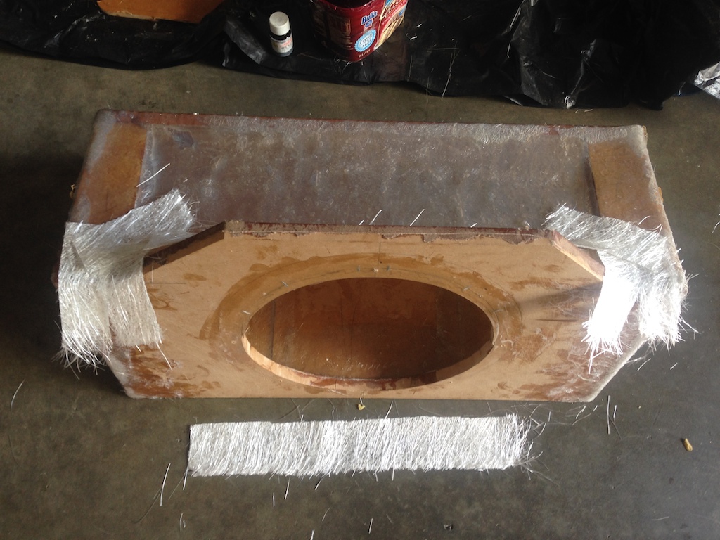
Once the template was done, I cut the 18mm MDF front section out, measured out the hole for the subwoofer and cut that out too.
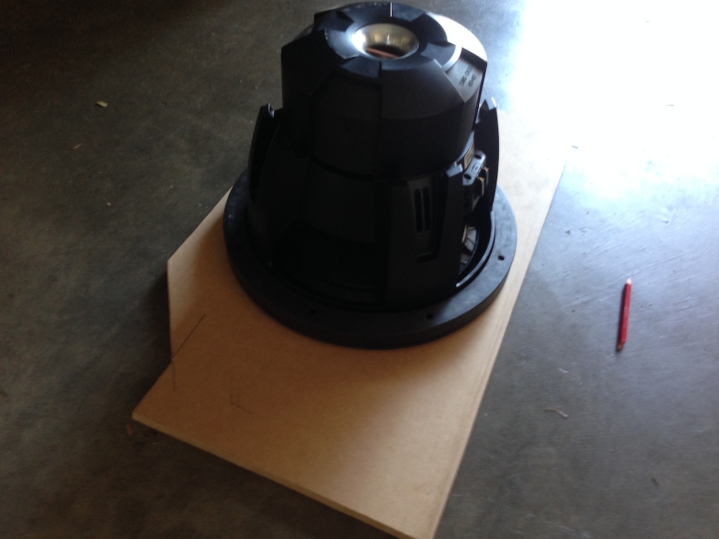
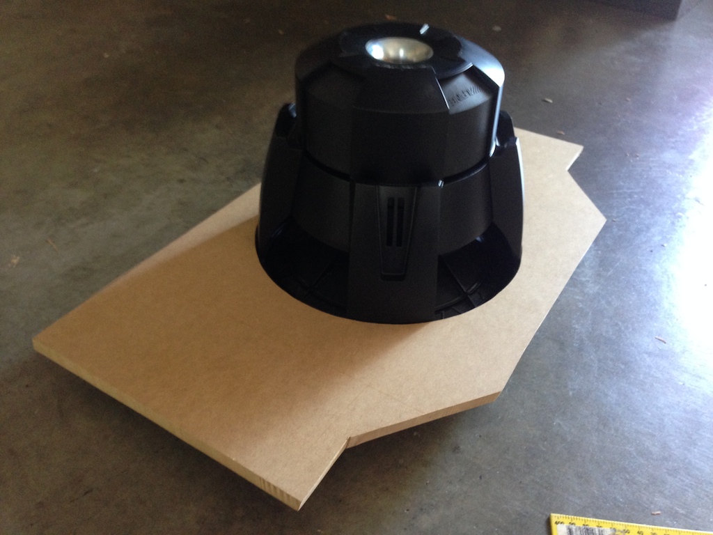
Then it was time for a test fit.
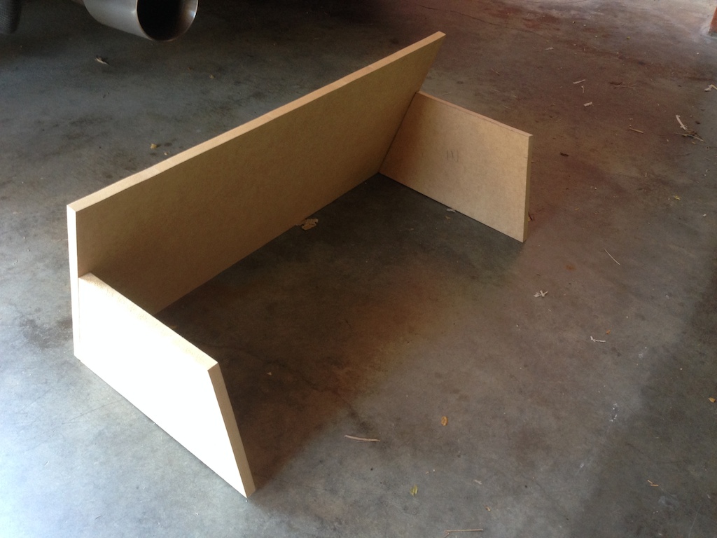
I measured up and cut the rear section to size out of 12mm MDF. The bit of MDF screwed into it is just to keep it in place while marking out the sides that are going to make up the frame of the box.
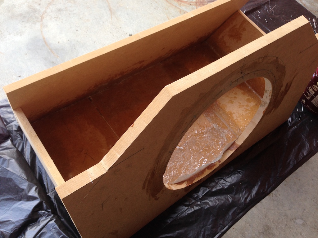
With the side sections marked out and cut, they're attached to the rear.
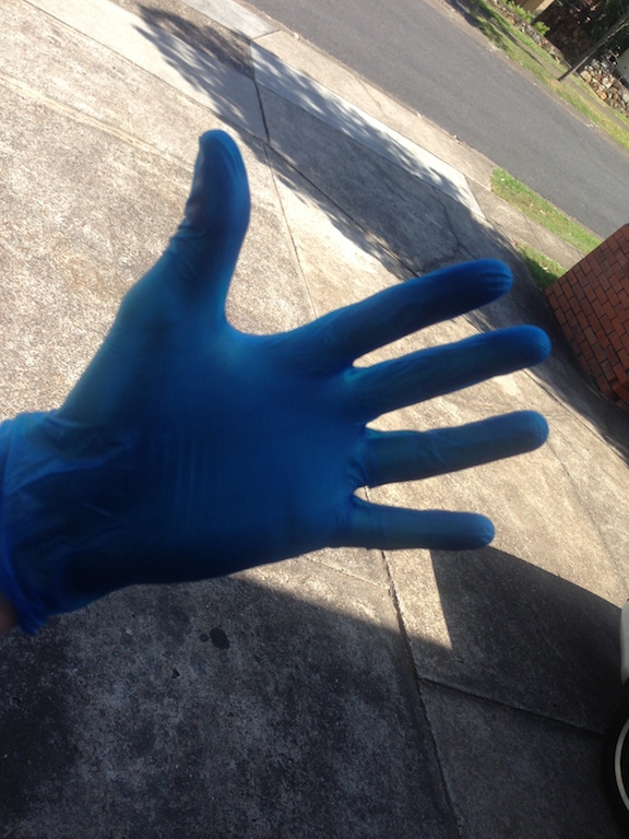
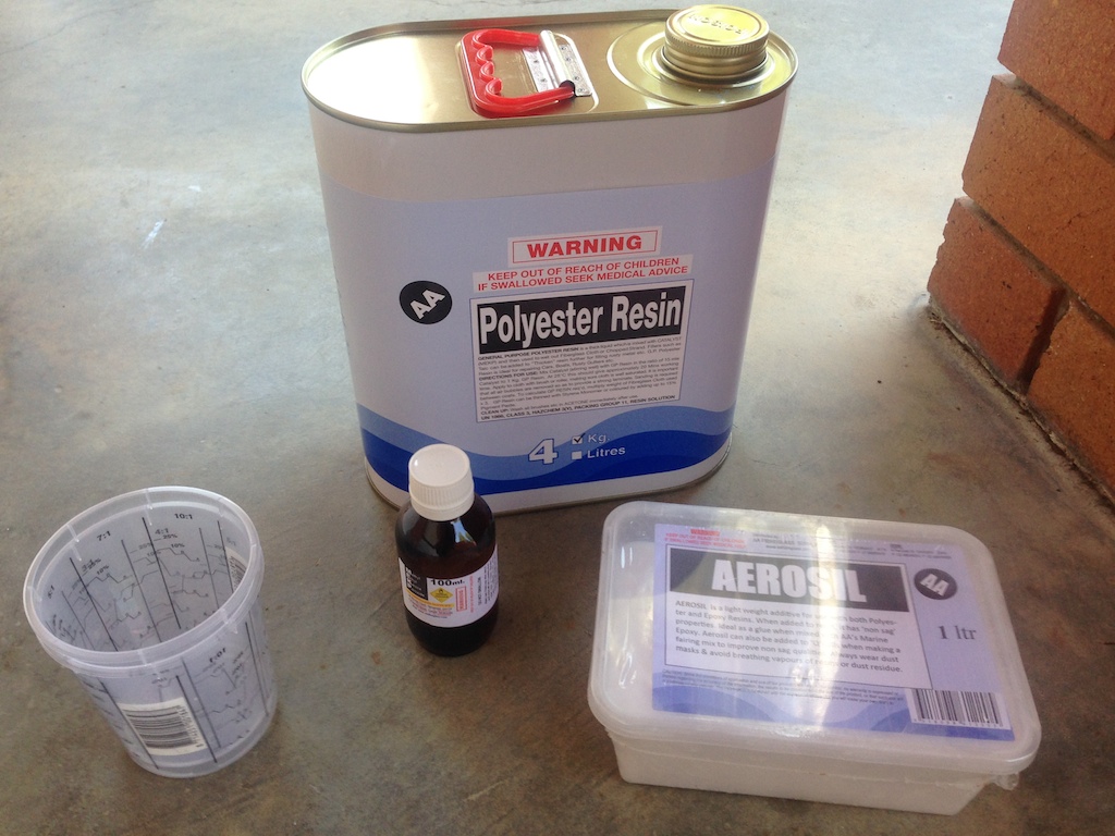
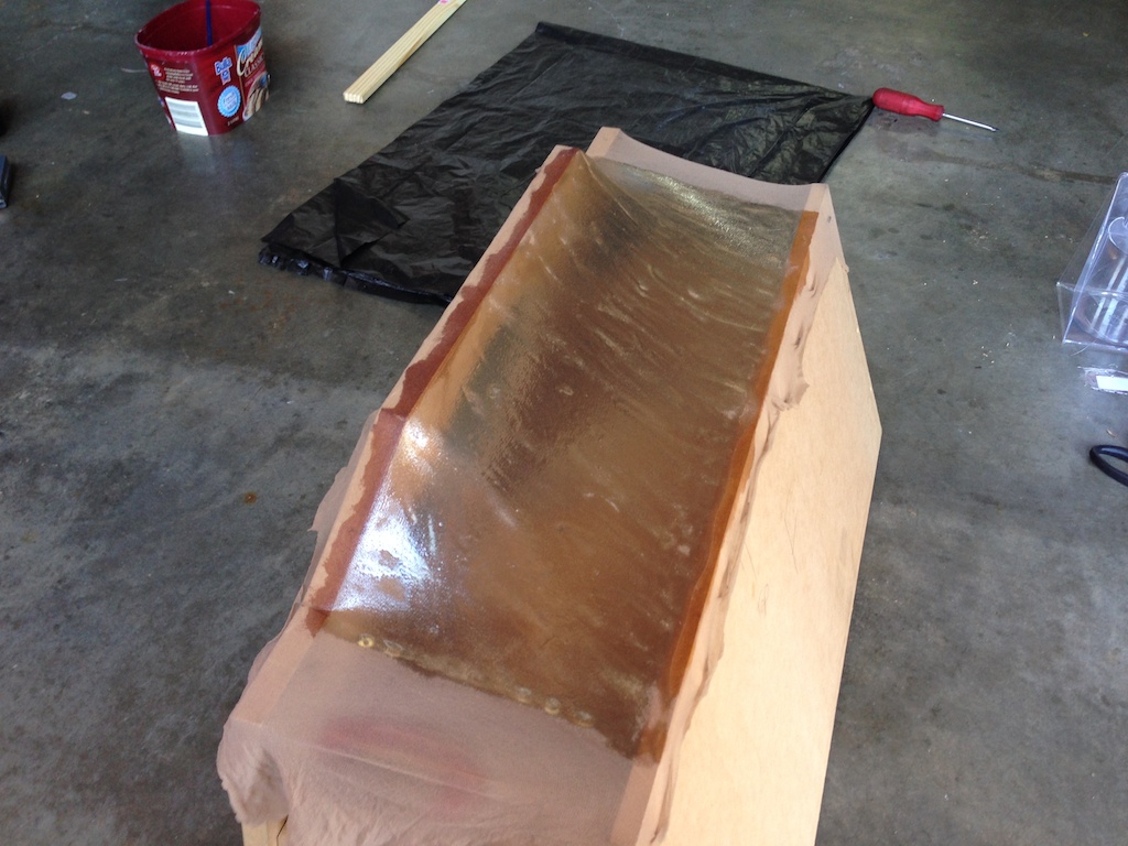
At this point it was time to start using the fibreglass and resin so some precautions were in hand...
The bottom of the box was made out of scraps, so came in 3 sections, the middle one was fibreglassed in right inside the boot itself, with a plastic sheet covering the boot so it didn't stick.
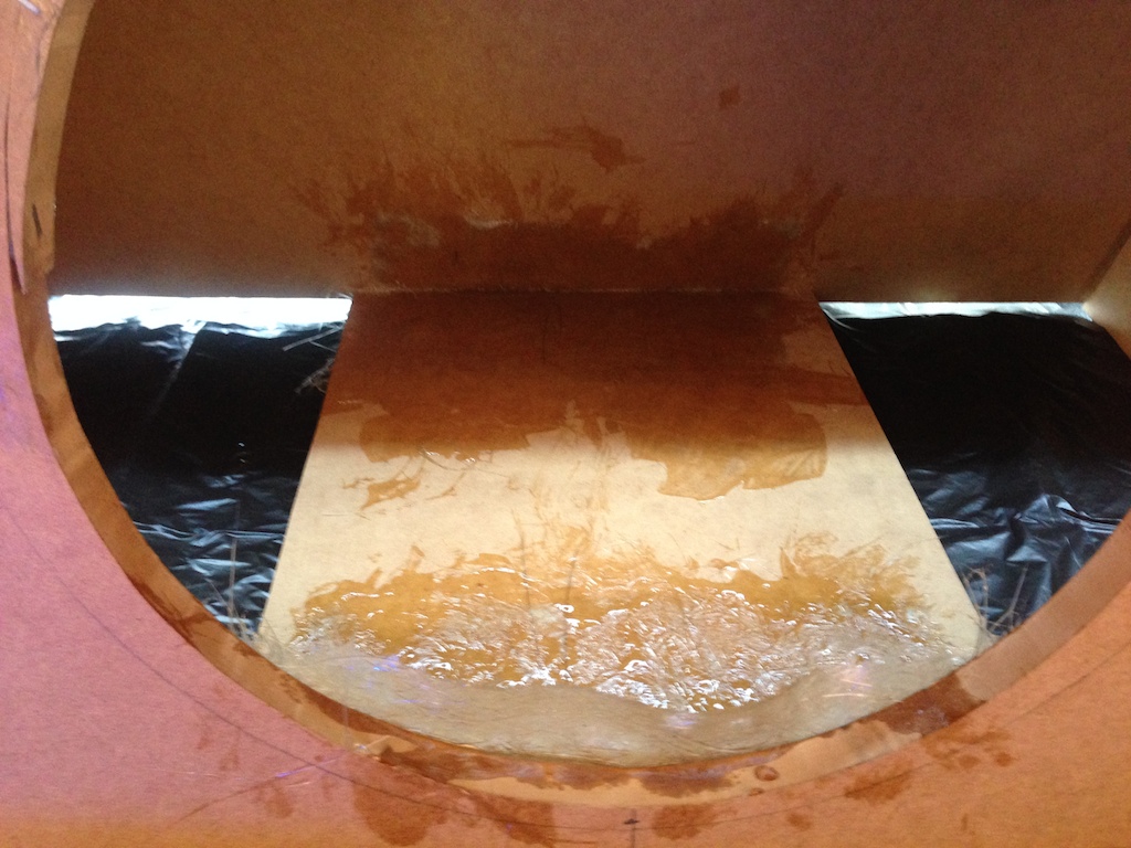
Later on I added the other two bits and more fibreglass all around the edges.
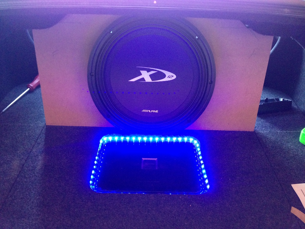
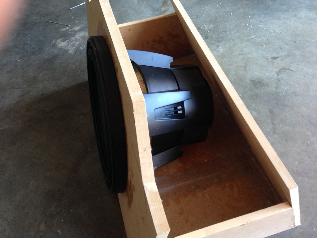
Test fitting the subwoofer, there's plenty of space there.
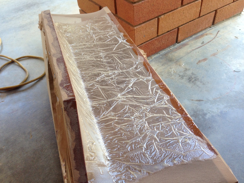
The next part was a bit of a challenge, the top section. This had to be custom fit to the shape of the boot, it had curves and couldn't be easily made out of MDF. The solution, some stockings stretched over the box, resin spread over them, then covered with plastic and placed into the boot to match exactly where the box will ultimately sit. This gives the exact shape we are after.
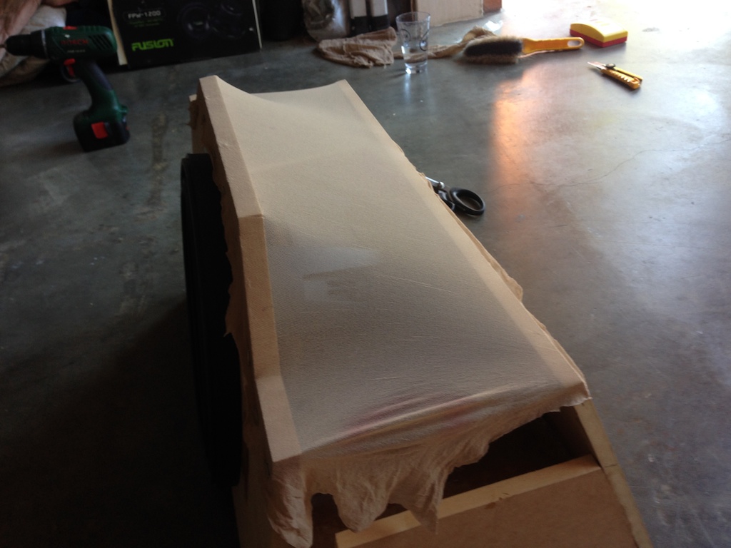

Once dry and the plastic removed, it was more or less what I wanted, albeit a little rough, but I could fix this later on as it needed many more layers of fibreglass before it was ready.
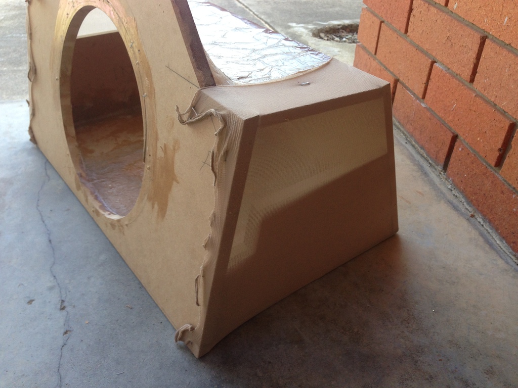
Same treatment was done for the sides.
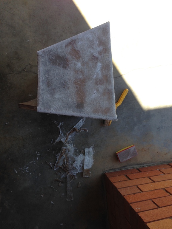
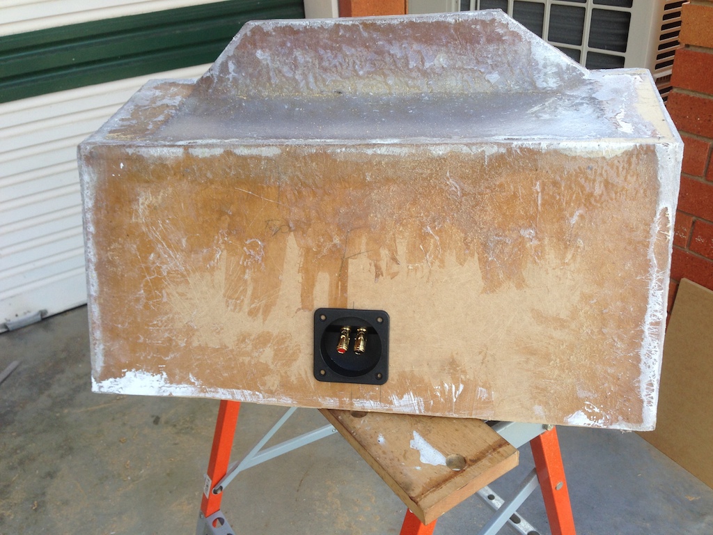
Eventually I added all the needed layers of fibreglass and sanded it down to the right shape.
The top needed more work to reinforce it. The bubbles seen there aren't important because the resin was added on the inside of the box, the outside was acting as a frame only.
To get the sides straight, I mixed the Aeorsil with the resin and let gravity do the work by pouring it on the side and letting it settle.
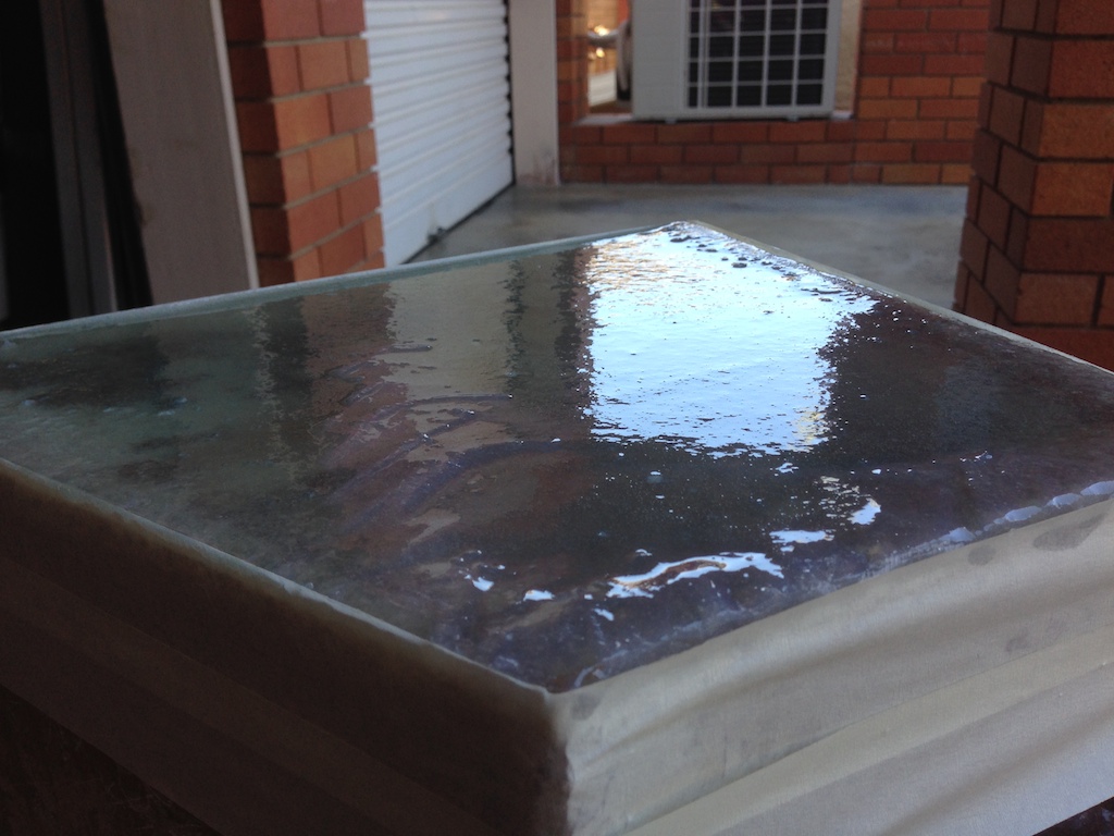
The aerosil mix went on top of the enclosure too. I've cut the speaker terminal connectors in at this point as well.
The next post deals with some internals of the enclosure and carpeting, plus the final finish for the install.
Update: Part 4 is here.
-i
