6-Sep-2015
Back when I bought my
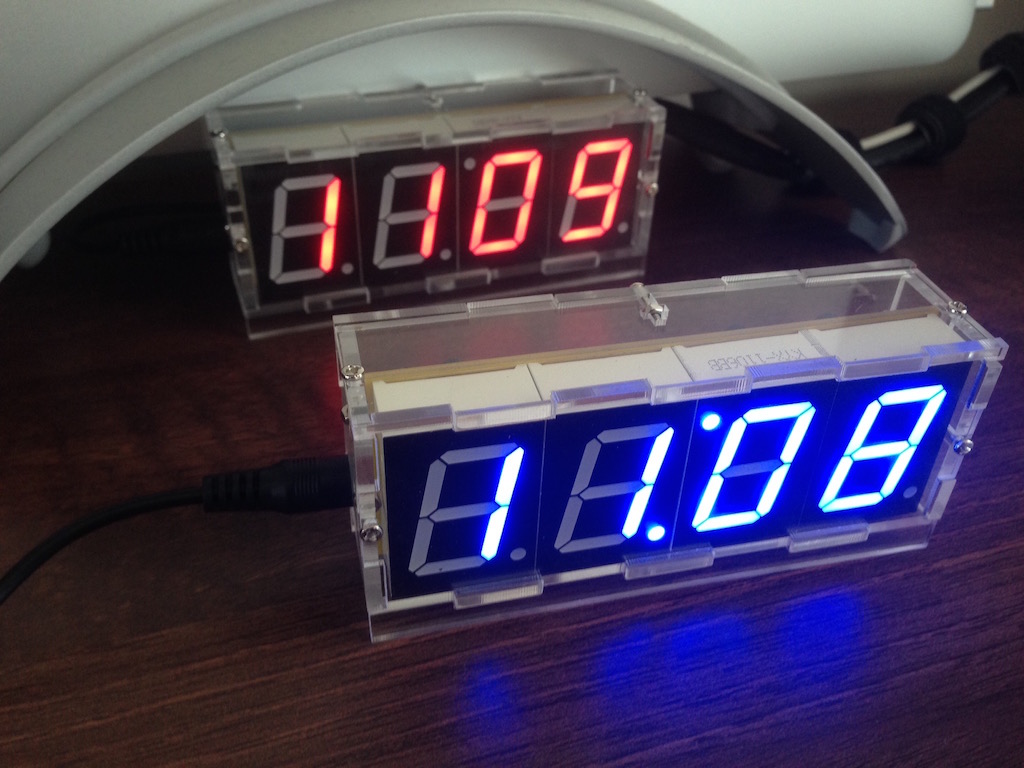
DIY 4 Digita LED Clock Kit, I picked up two - one red and one in blue. Unfortunately only one case was shipped with that order. With days to spare before Father's Day, the missing case finally turned up. I put the blue version of the clock together much faster this time, but I also took a different approach to how I soldered it.
The blue version is much brighter than the red.
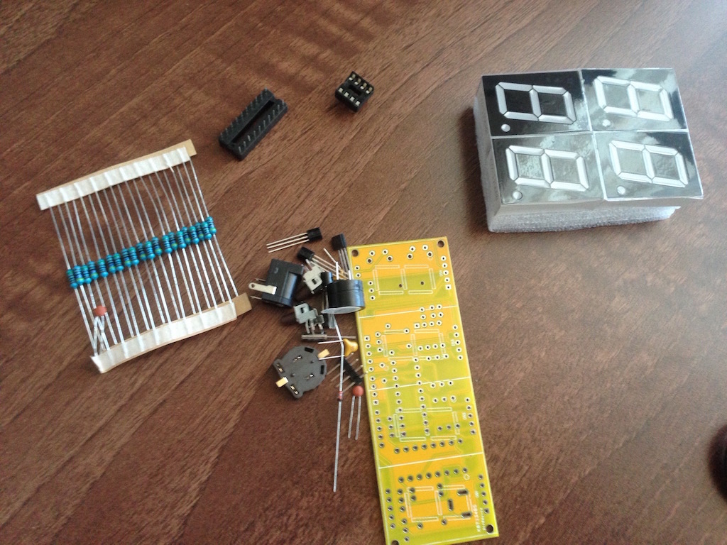
The components were the same more or less. The blue kit had fewer left over parts after assembly however.
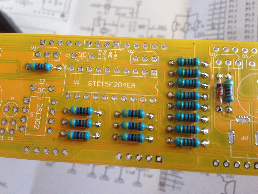
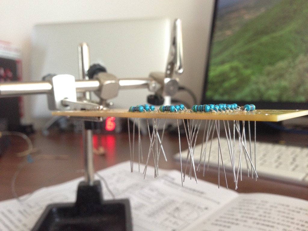
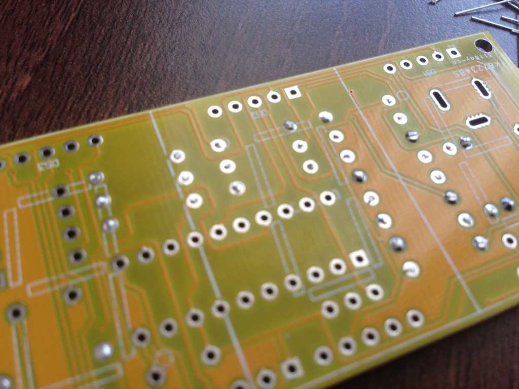
Because I was in a hurry to put this one together, I decided to solder as many components as possible from the top side after placing them in their correct spots. This saved quite a bit of time. With the resistors and diode it was pretty much trivial, the capacitors had to be soldered from the bottom still and the transistors were done 2 pins top and the middle pin bottom.
Some of the solder still came through on the bottom side, but that's not a big deal.
The clock now sits in my dad's new office room at the parents' house. This is the last kit of this sort that I have. The
custom PCBs that I've designed are on the way though! Those will be used to construct another clock-type device soon.
-i
A quick disclaimer...
Although I put in a great effort into researching all the topics I cover, mistakes can happen.
Use of any information from my blog posts should be at own risk and I do not hold any liability towards any information misuse or damages caused by following any of my posts.
All content and opinions expressed on this Blog are my own and do not represent the opinions of my employer (Oracle).
Use of any information contained in this blog post/article is subject to
this disclaimer.
Igor Kromin