This article is split into five parts, as each part becomes available I'll link to it below.
I realised that after publishing and sharing this article that I typed in LED instead of LCD! Please bear with this typo!
The final piece of work was to install McWill's LCD screen kit into my Lynx. This mod wasn't cheap (95€ + 15€ shipping) but made a huge difference to the quality of the graphics that the Lynx produced. It literally transformed my 20 year old console to something that was on par with the Nintendo DS.
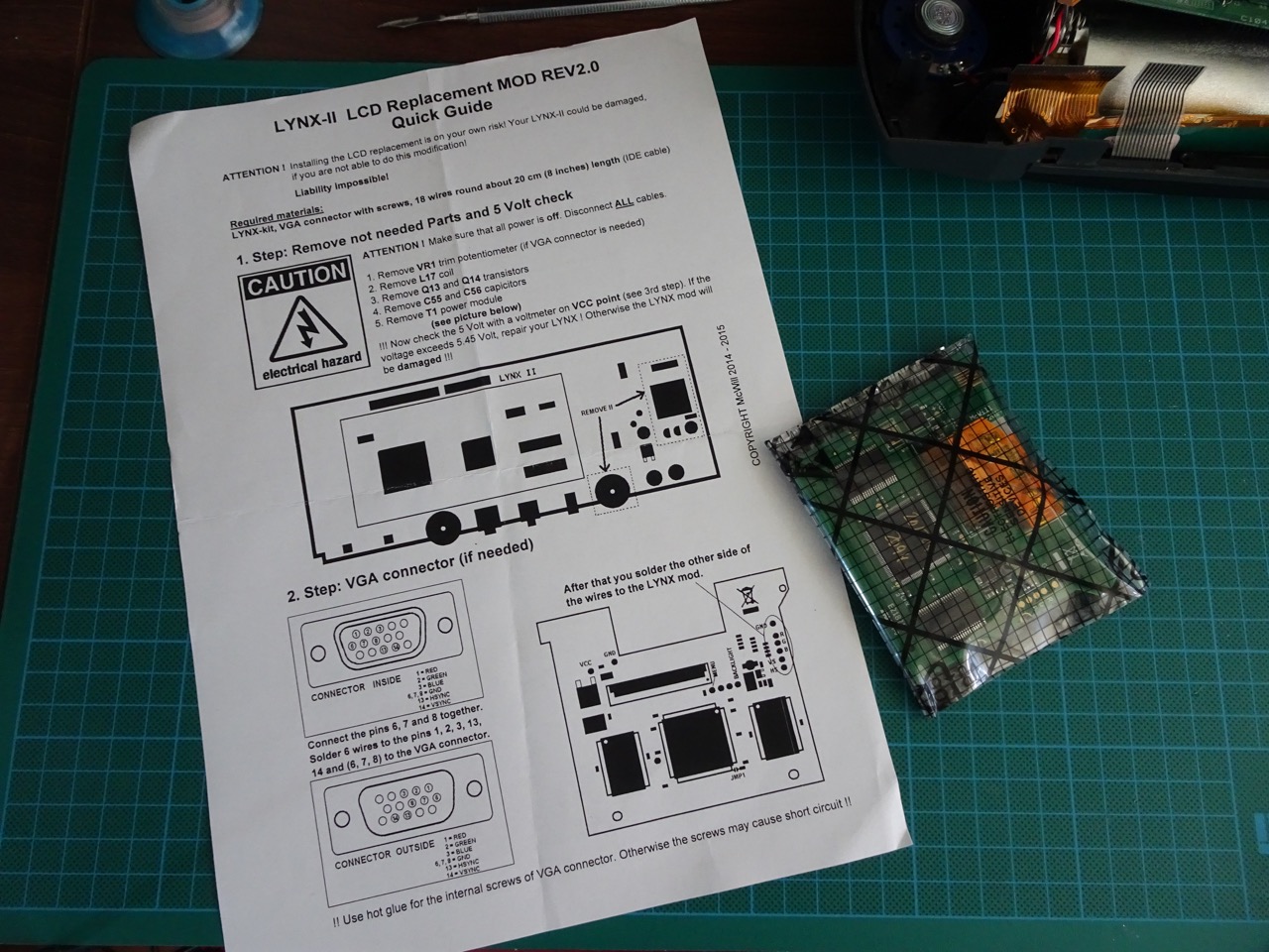
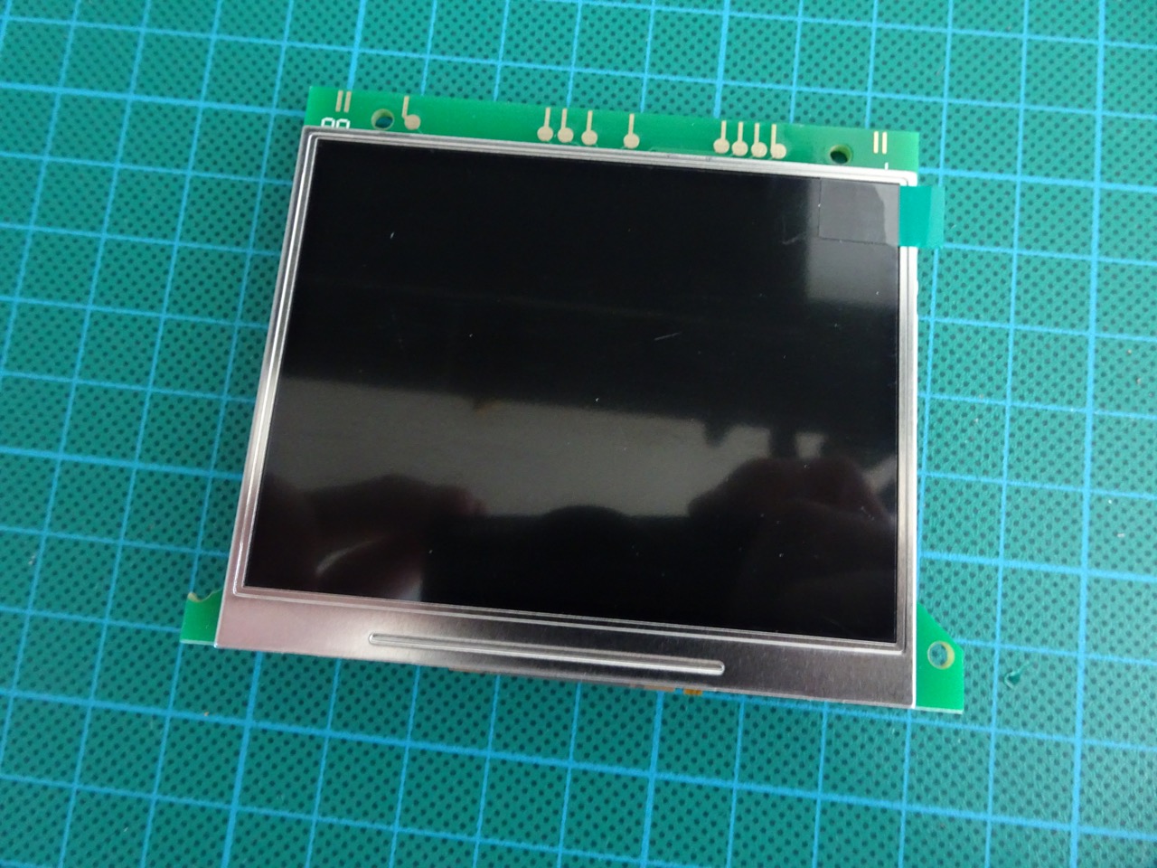
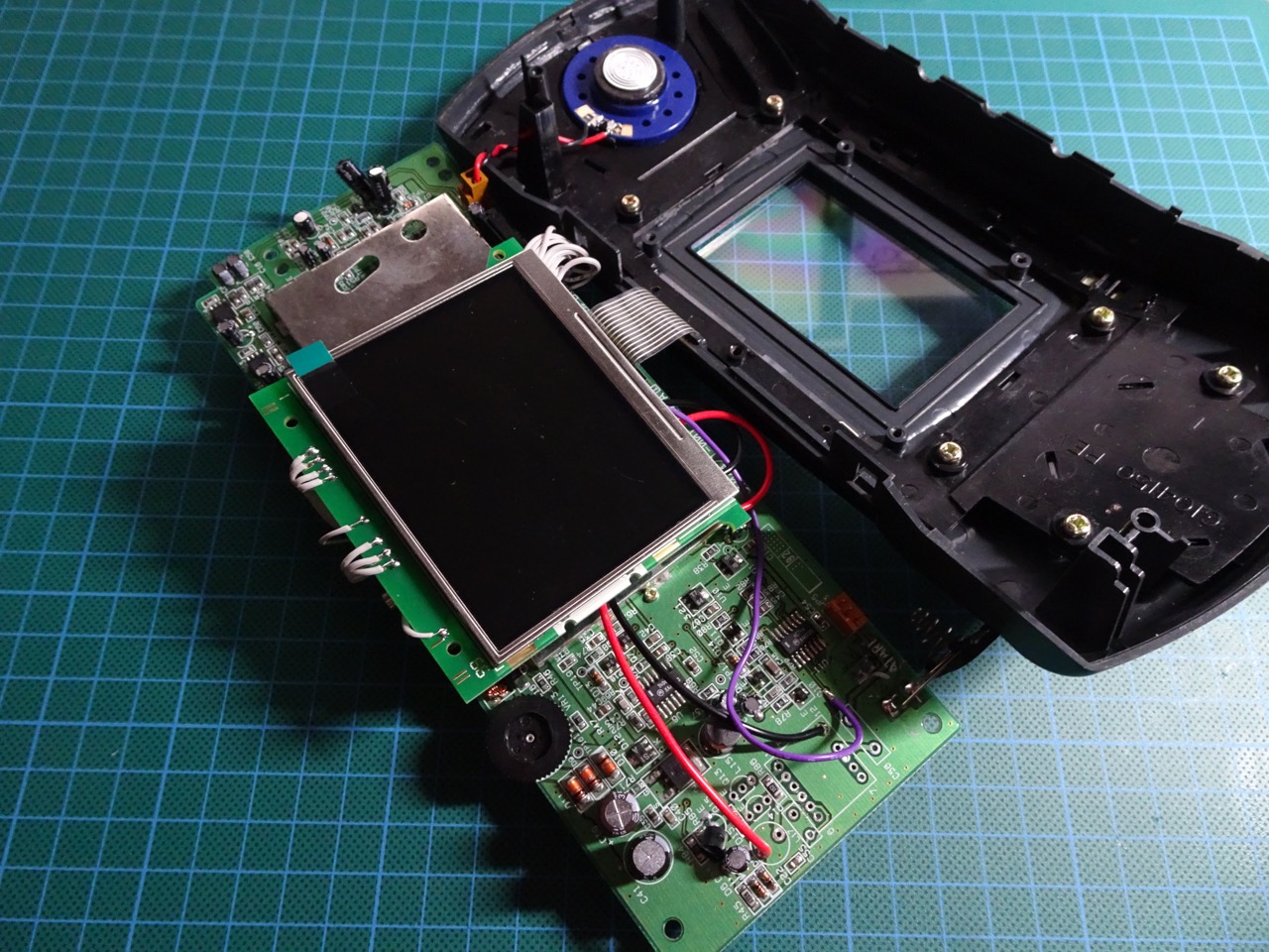
I received revision 2.0 of the kit, not sure what the earlier kit was like but this one was made up of the main board with its LCD screen. It also came with a VGA connector which I didn't use since I didn't want to cut into my Lynx. The instructions were just a single sheet of paper. They were mostly easy to follow though I will note some discrepancies further down that had me stumped in places.
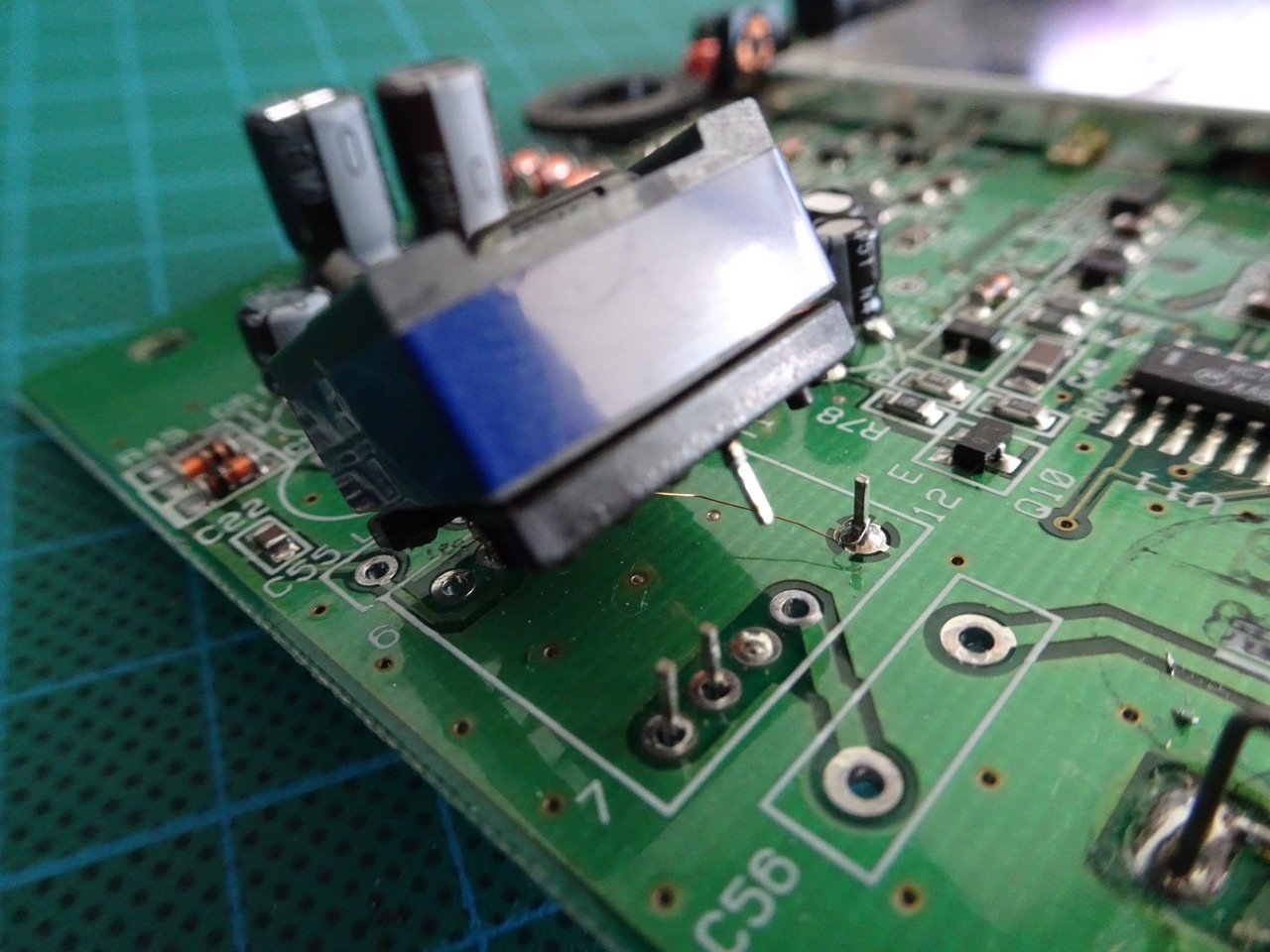
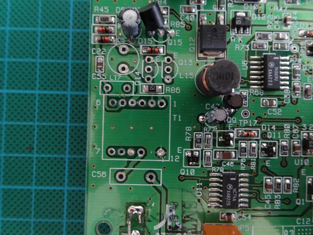
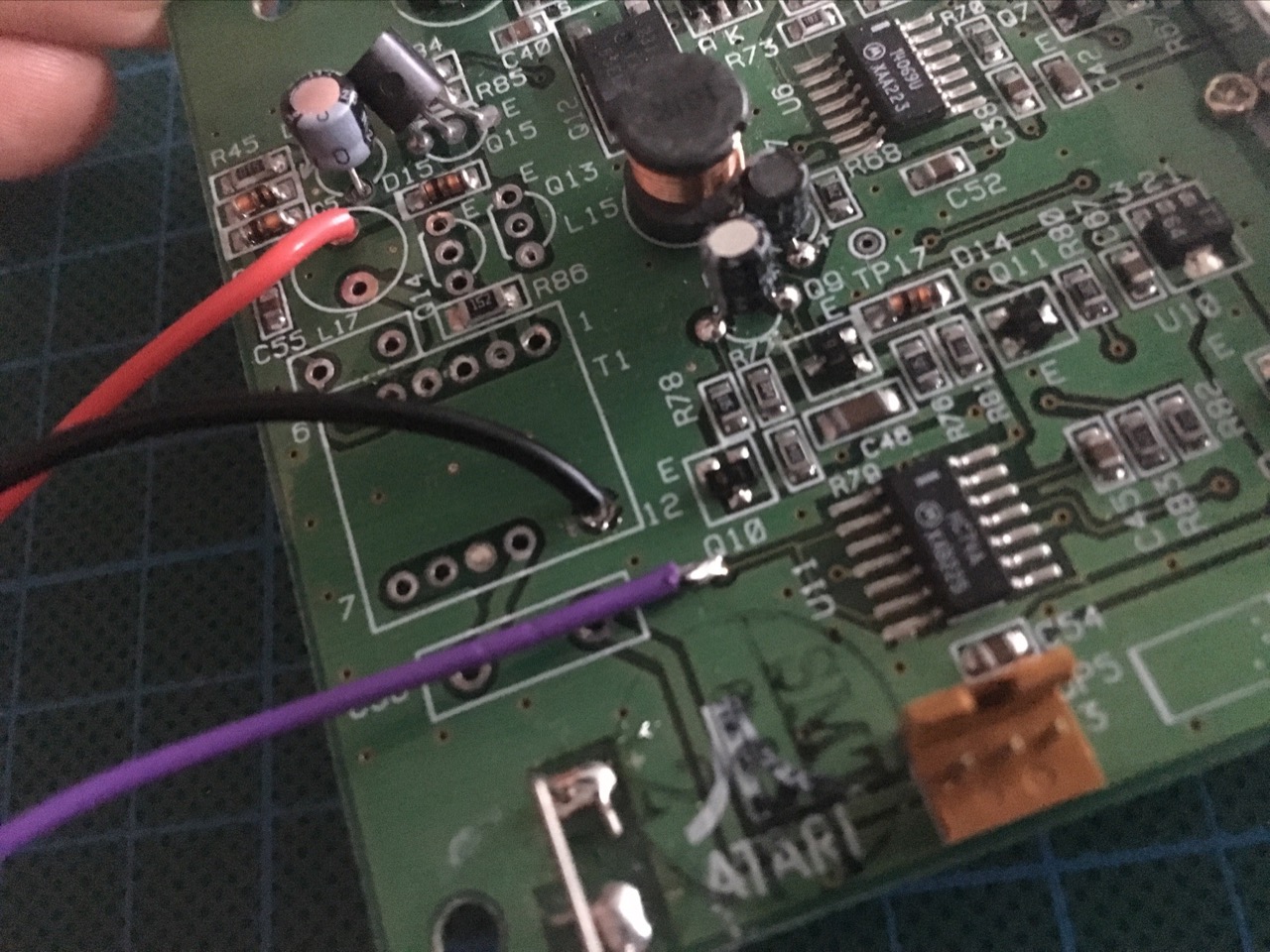
The first step in installing this kit was to remove some unneeded components from the Lynx motherboard. Out came the desoldering wick again! These components were what I assumed a part of the high voltage circuitry required to drive the lighting tube on the Lynx's original screen.
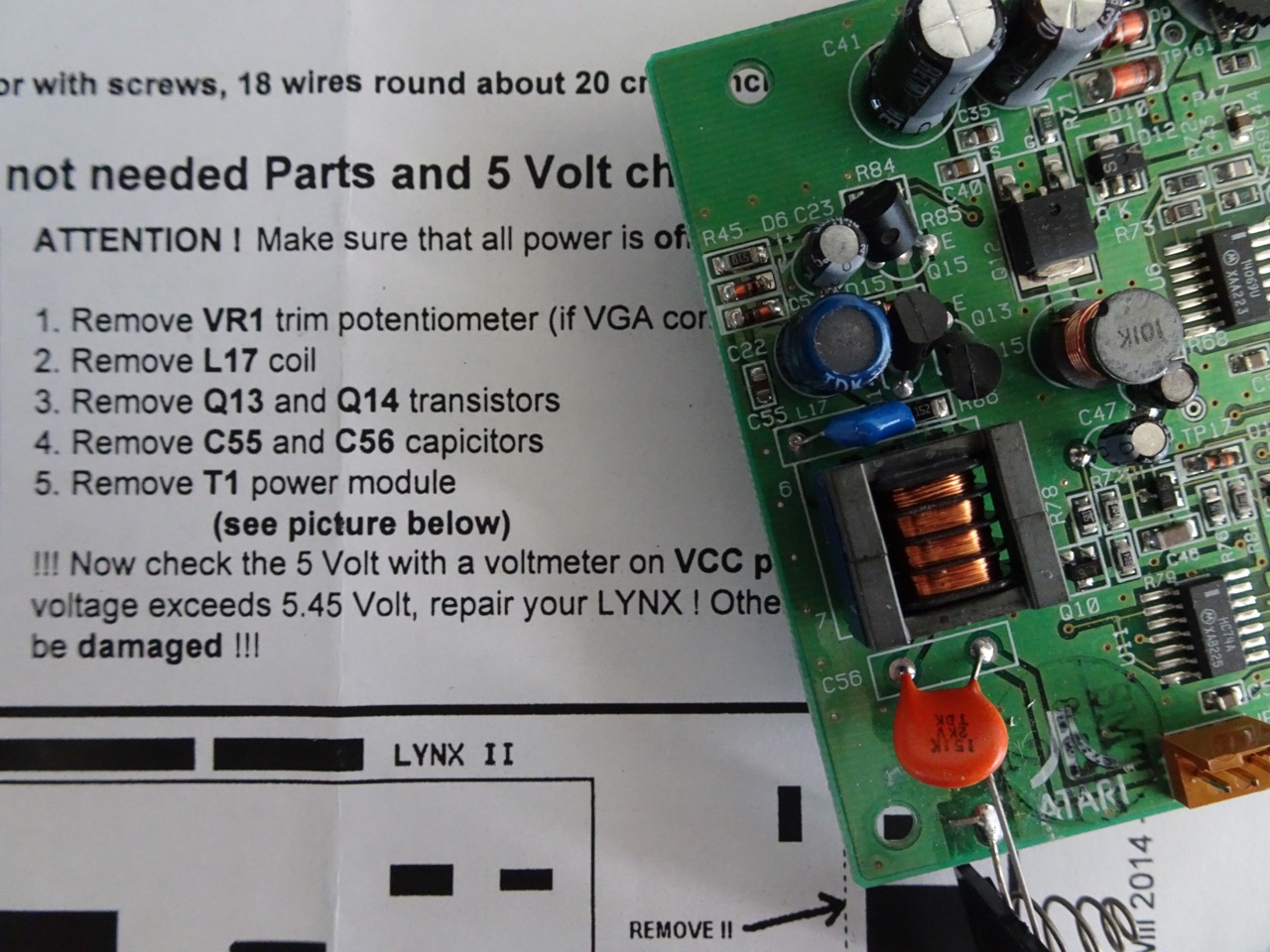
The T1 module was the most difficult to remove. I wanted to try and preserve it, but couldn't find a way of removing it without damaging it. Oh well. The rest of the components came out pretty easily and I was able to keep those intact.
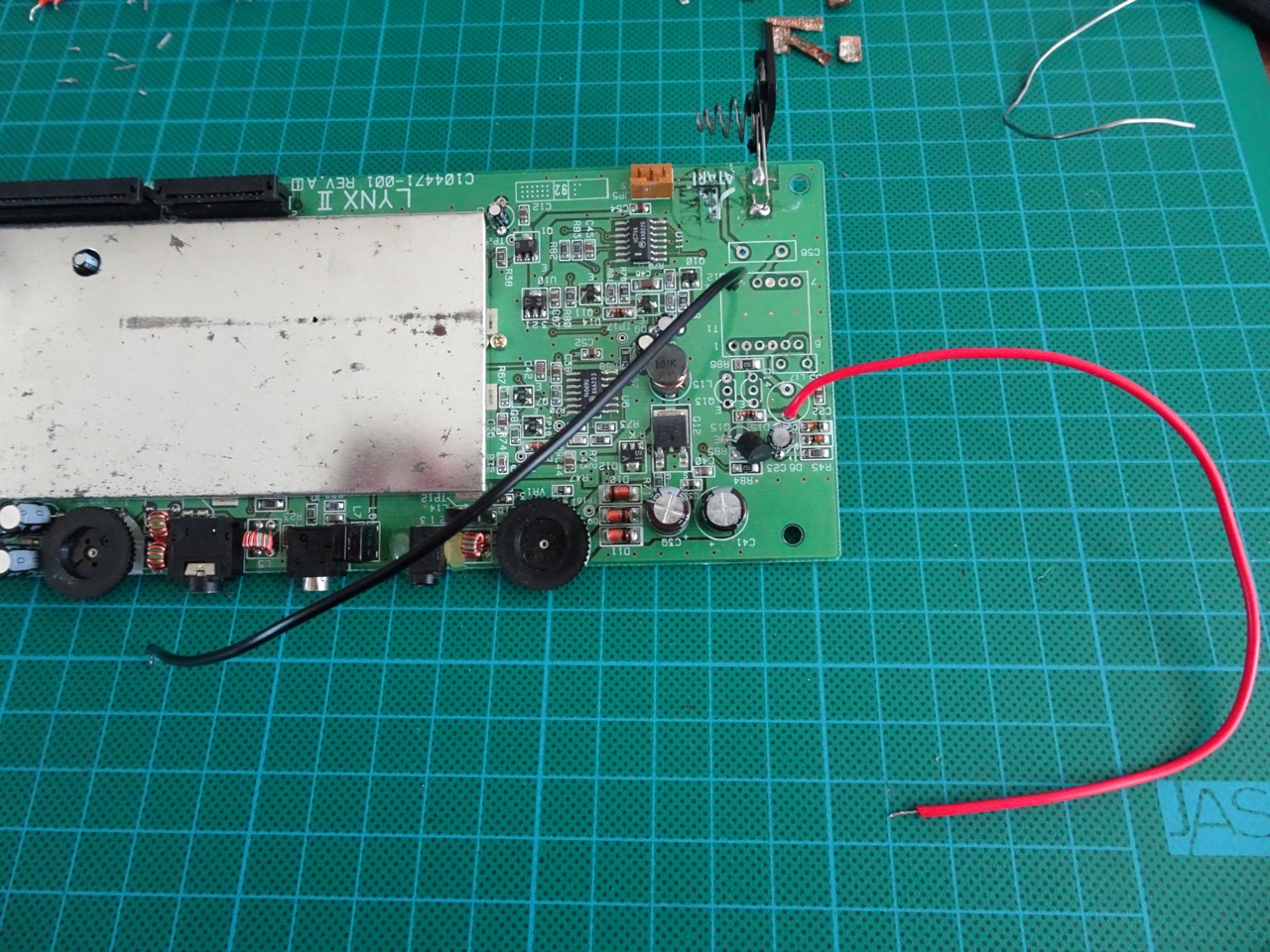
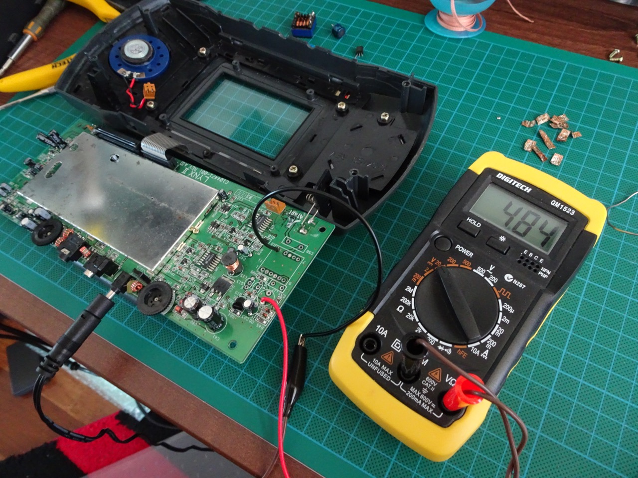
After removal of the components I soldered in two lengths of wire, for the GND and VCC connections. This is when I had to measure the voltage that the motherboard was generating. This step could have been explained a little more I thought since it required me to re-connect the front shell ribbon cable so that the Lynx could be turned on.
The voltage on mine measured at 4.84V which was close enough to the 5V expected voltage. It didn't exceed the 5.45V figured mentioned in the instructions so I moved on, no additional repair was necessary!
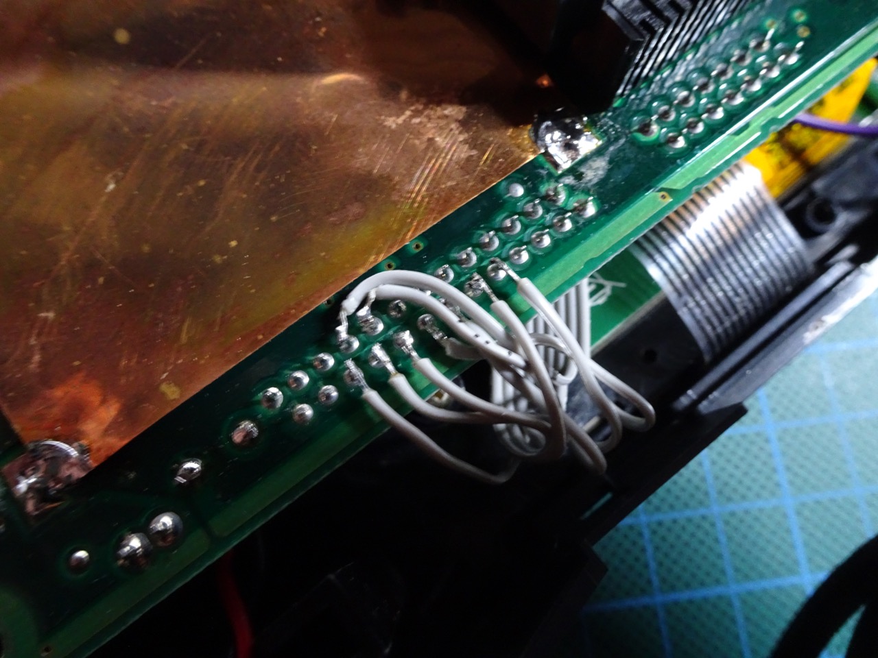
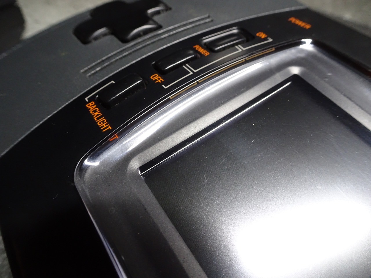
The backlight button wiring instruction was also not the best. I wired the (purple) backlight wire as directed on the LCD screen board, this was easy. The harder part was wiring the other end on the Lynx motherboard. Instructions said to attach it to Pin 2 on the U11 IC. This is an SMD mounted component and is next to impossible to solder to directly due to its small size. Luckily there was a trace coming off Pin 2 that went to a via. I used some left over legs from the earlier re-capping part of this project to solder into the via first, then I soldered the backlight button wire to this leg. This was a much easier way to attach this wire versus trying to attach it directly to the IC.
I also connected a short wire between the MENU pad and GND since I was not installing the VGA connector.
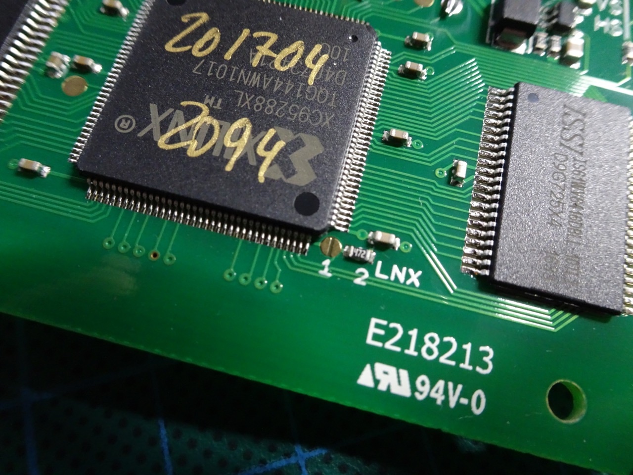
More confusion followed when I read about connecting the RES or TPR pins. There was mention of some jumper - "For using TPR jumper is closed, for using RES jumper is open!" Ok I had no clue where this jumper was as there was no obvious jumper header or anything else in the instructions that highlighted where this jumper would be. Eventually I worked out that this was a reference to the two pads on the IC side of the board marked as LNX.
I wasn't exactly sure whether I should use the RES or TPR pins on the Lynx motherboard to connect to the LED screen board. The difference between these was not explained, just that I should use one or the other. In the end I decided that since I didn't have the C104129-001 version of the Lynx motherboard (as mentioned in the instructions), I would stick with the RES pin. This also meant that the LNX pads were left alone, no need to short them out i.e. the jumper was open.
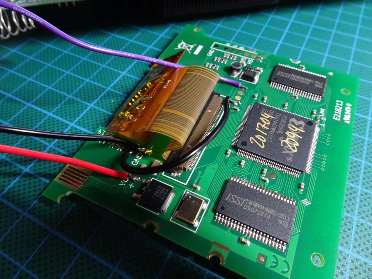
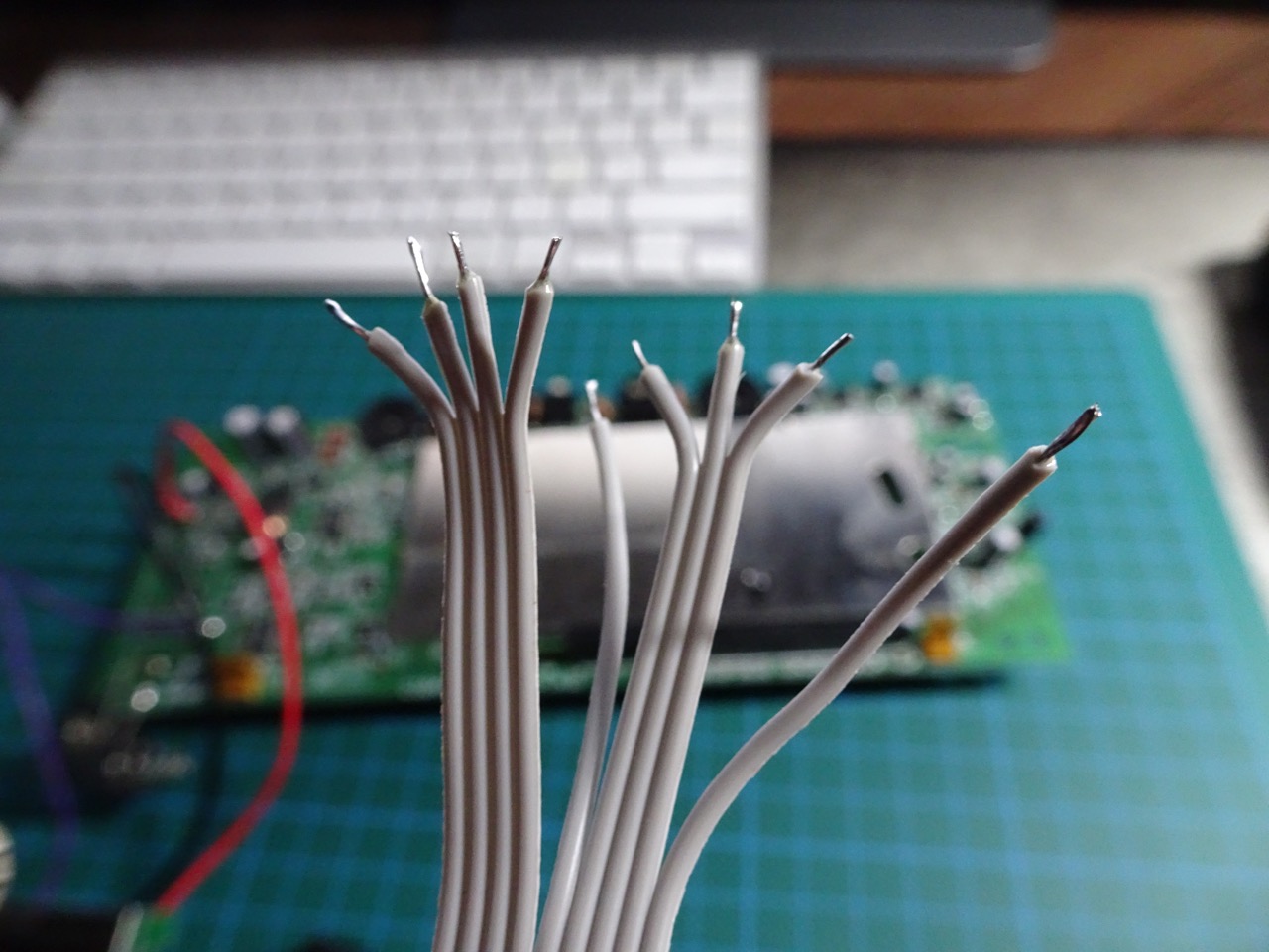
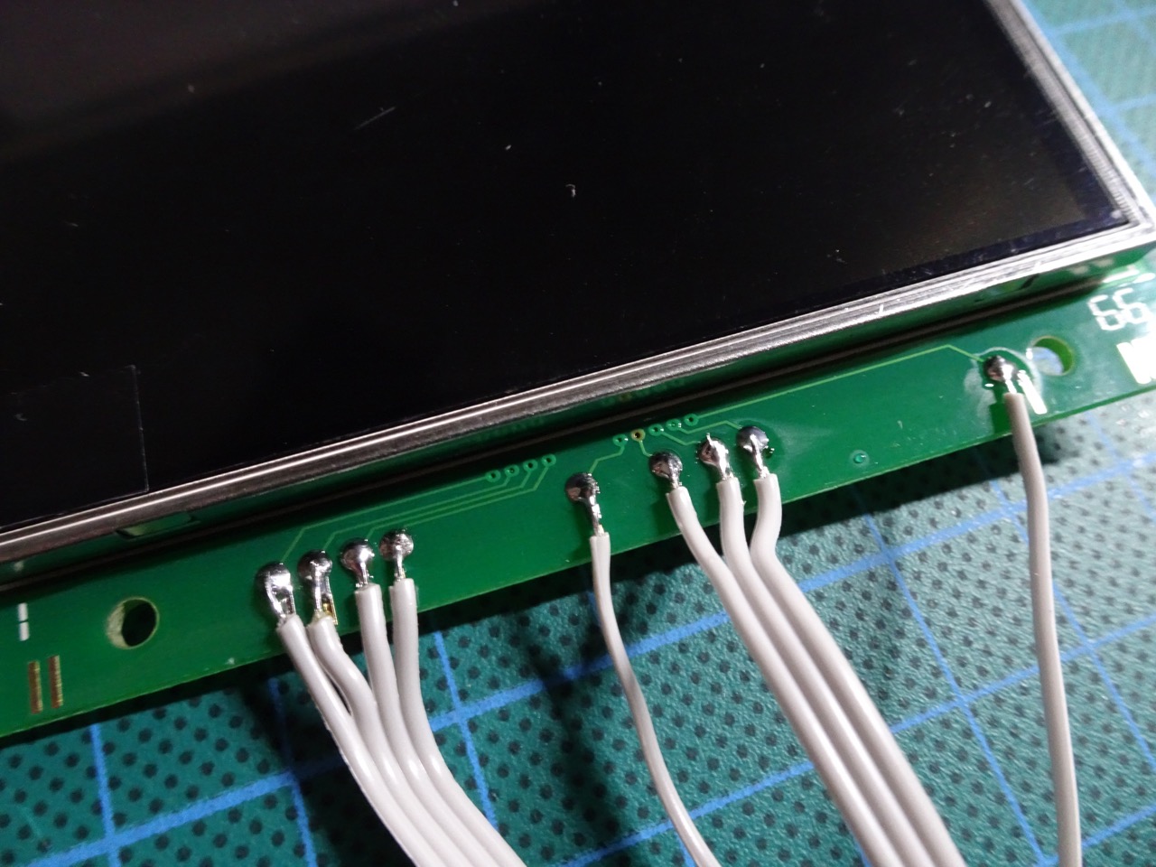
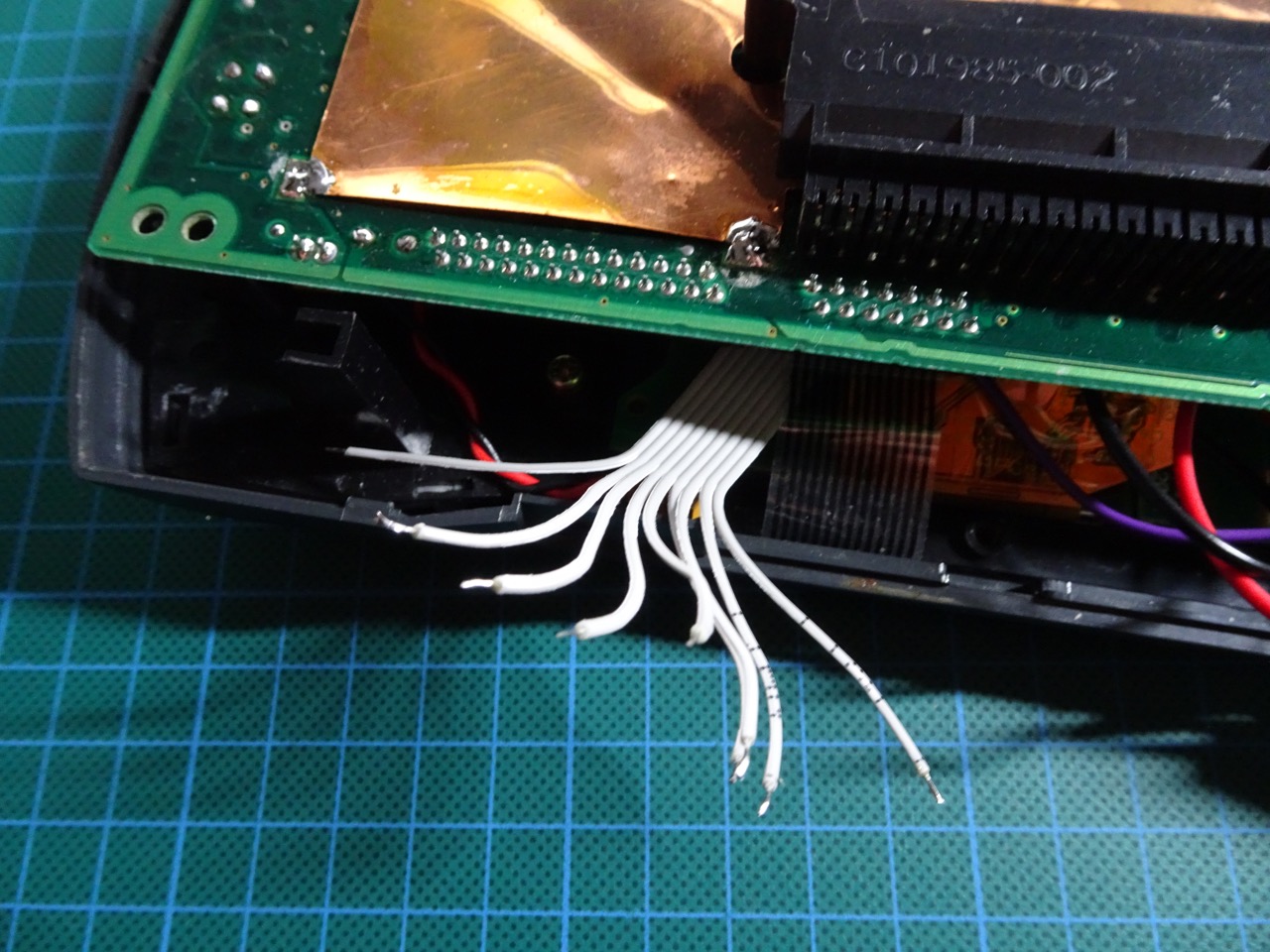
The next part was connecting the remaining 9 wires between the Lynx motherboard and the LED screen board. I used a ribbon cable that I had laying around. I somehow managed to cut it to the exact length that would stretch between the two boards and would still give me room to wire them together. I should have done a dry fit to determine the size of the cable first so I could have some more slack because it was a little tricky doing some of the wiring with the length of the cable I had. It worked out ok in the end though.
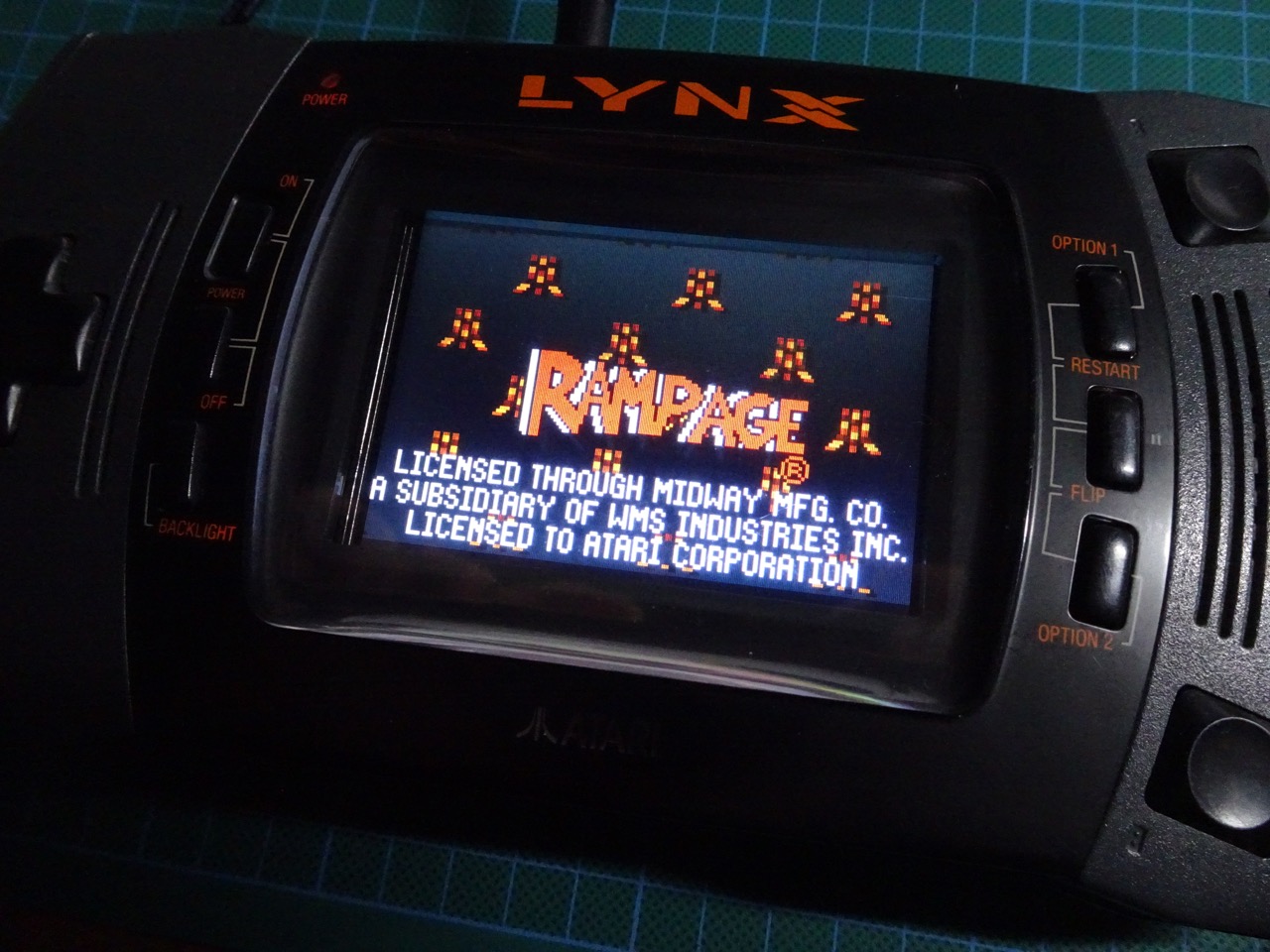
Now everything was wired up it was time for a test run. With the Rampage cart in...power on...I saw a mess of multi-coloured pixels. My heart started to sink but then the graphics from the game popped up in their full glory! Phew, I guessed that was just garbage data being shown after a cold boot of the system (further testing showed this happened every time the Lynx was powered on even if it was on just seconds prior).
I was amazed by how good the screen looked now. It was so much better than the original it just blew my mind. The photo below doesn't do it justice.
Now that everything was confirmed working it was time to re-assemble the console.
One issue I noticed was the left side of the screen showed a part of its metal frame. Not sure if this was due to me not aligning it properly during installation. The other Lynx 2 I have that still has its original screen also has a similar stripe where you can see a tiny slither of the metal around its screen too, so I'm guessing this is expected. At some point I will take the Lynx apart again to see if I can fix this.
So that's it for the repair of my Lynx 2. It took a whole full day but was a fun little project. Over the coming months I plan to compare how some games look on this modded Lynx 2 vs one of my other Lynxes that still has the original screen.
-i
